
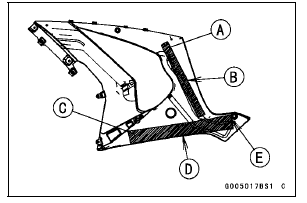
When installing the pad [A], align the edge of the pad and the marking of the fairing [B].
When installing the pad [C], align the edge of the pad and the fairing [D], and fit the edge of the pad to the boss [E].
Insert the hook portions [A] into the slots.
Insert the front hook [B] first, then insert the remainder sequentially.
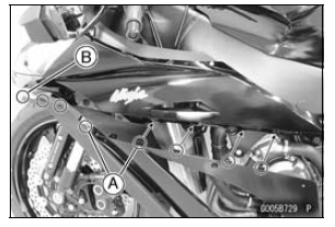
 Lower Fairing Removal
 Upper Fairing Assembly Removal
DFI System Wiring Diagram
Part Names
1. Air Intake Solenoid Valve (Other than US, CA and CAL Models)
2. Front Wheel Rotation Sensor
3. Engine Stop Switch
4. Starter Button
5. Air Switching Valve
6. Stick Coil #1, #2, #3, #4
7. Spark Plugs
8. Intake Air Temperature Sensor
9. Crankshaft Sensor
10. Secondary Fuel ...
Front Fork Oil Change
Remove the front fork (see Front Fork Removal (Each
Fork Leg)).
Turn the spring preload adjuster fully counterclockwise for
removing the piston rod assy easily.
Hold the inner tube lower end in a vise.
Using the wrench [A], unscrew the top plug [B] out of the
outer tube.
Special Too ...
Oil Pump Installation
Install the outer rotor [A] into the crankcase.
Assemble:
Oil (Water) Pump Shaft [B]
Pin [C]
Inner Rotor [D]
To prevent dropping, apply grease to the pin.
Install the inner rotor assembly into the crankcase.
Fit the slot [E] onto the projection [F].
Replace the O-ring [A ...