
NOTE
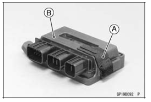
The relay box has relays and diodes. The relays and diodes can not be removed.

Relay Box Installation
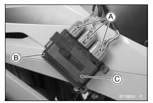
Stick the pad [A] to the rubber protector [B] as shown in the figure.

 Relay Box
 Relay Circuit Inspection
Steering Stem Bearing Lubrication
Remove the steering stem (see Stem, Stem Bearing Removal
in the Steering chapter).
Using a high flash-point solvent, wash the upper and
lower ball bearings [A] in the cages.
Wipe the upper and lower outer races which are press
-fitted into the head pipe to clean off grease and dirt.
V ...
Stopping the engine
Close the throttle completely.
Shift the transmission into neutral
Turn the ignition key to “OFF”.
Support the motorcycle on a firm,
level surface with the side stand.
Lock the steering.
NOTE
The motorcycle is equipped with a
vehicle-down sensor, which causes
the engine to sto ...
Special Tools and Sealant
Hand Tester:
57001-1394
Flywheel Puller Assembly, M38 × 1.5/M35 × 1.5:
57001-1405
Peak Voltage Adapter:
57001-1415
Lead Wire - Peak Voltage Adapter:
57001-1449
Key Registration Unit:
57001-1582
Grip:
57001-1591
Flywheel & Pulley Holder:
57001-1605
Rotor Holder:
...