
NOTE
Be sure the battery is fully charged.
Special Tool - Throttle Sensor Setting Adapter: 57001 -1538

Subthrottle Sensor Input Voltage Connections to Adapter: Digital Meter (+) → W (sensor BL) lead Digital Meter (–) → BK (sensor BR/BK) lead
ECU Intake Air Temperature Sensor
Input Voltage
Standard: DC 4.75  5.25 V
If the reading is within the standard, check the output voltage (see Subthrottle Sensor Output Voltage Inspection).
If the reading is out of the standard, remove the ECU and check the wiring for continuity between harness connectors.
Special Tool - Hand Tester: 57001-1394
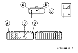
Disconnect the ECU and sensor connectors.

Wiring Continuity Inspection ECU Connector [A] ←→ Subthrottle Sensor Connector [B] BL lead (ECU terminal 9) [C] BR/BK lead (ECU terminal 13) [D]
If the wiring is good, check the ECU for its ground and power supply (see ECU Power Supply Inspection in the Fuel System (DFI) chapter).
If the ground and power supply are good, replace the ECU (see ECU Removal/Installation in the Fuel System (DFI) chapter).
 Subthrottle Sensor Removal/Adjustment
 Subthrottle Sensor Output Voltage Inspection
For Secondary Fuel Injectors
Remove the fuel tank (see Fuel Tank Removal).
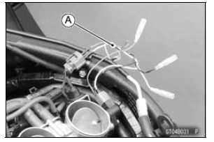
Disconnect the secondary fuel injector connector [A].
Connect a digitalmeter to the terminals in each secondary
fuel injector [A].
Measure the secondary fuel injector resistance.
Secondary Fuel Injector Resistance
Standard: Abo ...
Front Wheel Rotation Sensor Signal Abnormal (Service Code b 42)
Measure the air gap between the front wheel rotation sensor
and sensor rotor.
Thickness Gauge [A]
Air Gap
Standard: 0.4 1.6 mm (0.02
0.06 in.)
If the measurement is not the standard, check each part
for deformation and looseness and correct accordingly.
If the measurement is t ...
Seat Cover Installation
Installation is the reverse of removal. Note the following.
When installing the pad [A], install it along the corner [B]
as shown in the figure.
When installing the pad [C], align the ends [D], along the
corner [E], and wrap [F] the upper edge of the seat cover.
Install the damper [A] ...