
Apply grease to the oil seal lips.
Apply oil to the outer circumference of the oil seal so that it will go into place smoothly.
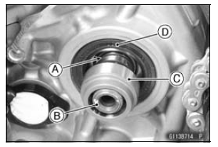
Install the oil seal to the crankcase so that the surface of the oil seal is flush with the surface of the crankcase.
Transmission Shaft Removal
Refer to the Transmission Assy Disassembly.
Transmission Shaft Installation
Refer to the Transmission Assy Assembly.
 Transmission Assy Assembly
 Transmission Shaft Disassembly
Electronic Steering Damper Warning Indicator Light
The yellow light functions as the
electronic steering damper warning indicator.
The light and warning symbol
"ESD" go on if there is a malfunction in
the electronic steering damper system.
However, this could also be caused by
trouble with the charging system (e.g.
battery). I ...
Fuel Reserve Switch Inspection
Fill the fuel tank with fuel and close the fuel tank cap.
Remove the front seat (see Front Seat Removal in the
Frame chapter).
Disconnect the fuel pump lead connector [A].
Connect the test light [A] (12 V 3.4 W bulb in a socket
with leads) and the 12 V battery [B] to the fuel pu ...
Intake Air Temperature Sensor Removal
NOTICE
Never drop the intake air temperature sensor especially
on a hard surface. Such a shock to the sensor
can damage it.
Remove the fuel tank (see Fuel Tank Removal in the Fuel
System (DFI) chapter).
Disconnect the connector [A] from the intake air temperature
sensor.
Remove the da ...