
Turn the oil seal side to the bottom.
Special Tool - Bearing Driver Set: 57001-1129
Turn the flat side to the bottom.
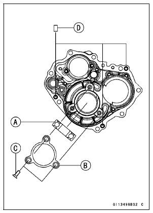
Turn the stepped edge to upside.
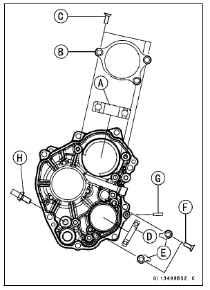
Special Tool - Bearing Driver Set: 57001-1129
Turn the flat side to the bottom.
Tighten: Torque - Transmission Case Bearing Holder Bolts: 4.9 N·m (0.50 kgf·m, 43 in·lb)
Turn the flat side to the bottom.
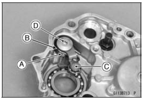
Spring [A] Washer [B] Gear Positioning Lever [C]
The shift fork [D] for drive shaft has “A2� mark. Turn the mark to the upside.
The shift forks [E] for output shaft have “A1� mark. Turn the mark to the bottom.
The shift forks [F] for output shaft have “A3� mark. Turn the mark to the bottom.
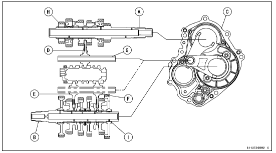
 Transmission Assy Disassembly
 Transmission Assy Installation
Exhaust Butterfly Valve Actuator Removal
NOTICE
Never drop the exhaust butterfly valve actuator especially
on a hard surface. Such a shock to the actuator
can damage it.
Remove:
Front Seat (see Front Seat Removal in the Frame chapter)
Clamp [A]
Screws [B] and Washers
Slide the covers [A] and loosen the lock nuts [B] ...
Shift Fork Guide Pin/Drum Groove Wear Inspection
Measure the diameter of each shift fork guide pin [A], and
measure the width [B] of each shift drum groove.
If the guide pin on any shift fork is less than the service
limit, the fork must be replaced.
Shift Fork Guide Pin Diameter
Standard: 6.9 7.0 mm (0.272
0.276 in.)
Service Limit: ...
For Primary Fuel Injectors
Remove the air cleaner housing (see Air Cleaner Housing
Removal).
Disconnect the injector connector and connect the harness
adapter [A] between these connectors as shown in
the figure.
Main Harness [B]
Primary Fuel Injector #1 [C]
Special Tool - Measuring Adapter: 57001-1700
...