
NOTE
Split the crankcase again, measure each clearance between the bearing insert and journal [B] using plastigage (press gauge).
Crankshaft Main Bearing Insert/Journal Clearance
Standard: 0.010  0.034 mm
(0.0004  0.0013 in.)
Service Limit: 0.06 mm (0.0024 in.)
If the clearance is within the standard, no bearing replacement is required.
If the clearance is between 0.035 mm (0.0014 in.) and the service limit (0.06 mm, 0.0024 in.), replace the bearing inserts [A] with inserts painted blue [B]. Check insert/journal clearance with the plastigage. The clearancemay exceed the standard slightly, but it must not be less than the minimum in order to avoid bearing seizure.
If the clearance exceeds the service limit, measure the diameter of the crankshaft main journal.
Crankshaft Main Journal Diameter
Standard: 34.984 35.000 mm
(1.3773  1.3780 in.)
Service Limit: 34.96 mm (1.3764 in.)
If any journal has worn past the service limit, replace the crankshaft with a new one.
If themeasured journal diameters [C] are not less than the service limit, but do not coincide with the original diameter markings [D] on the crankshaft, make new marks on it.
Crankshaft Main Journal Diameter Marks
None 34.984  34.992 mm (1.3773
 1.3776 in.)
1 34.993  35.000 mm (1.3777
 1.3780 in.)
 : Crankshaft Main Journal
Diameter Marks (“1” or No
Mark)
[A]: Crankcase Main Bearing Inside Diameter Marks, “” or no mark.
NOTE
The mark already on the upper crankcase half should almost coincide with the measurement.
Crankcase Main Bearing Inside Diameter Marks
38.000 38.008 mm (1.4961
1.4964 in.)
None 38.009 38.016 mm (1.4964
1.4967 in.)
Size Color [B]
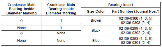
*: The bearing inserts for Nos. 2 and 4 journals have an oil groove, respectively.
 Crankshaft Runout Inspection
 Pistons
Wheels
Tubeless tires are installed on the
wheels of this motorcycle. The indications
of “TUBELESS” on the tire side
wall and the rim show that the tire and
rim are specially designed for tubeless
use.
A. “TUBELESS” Mark
A. “TUBELESS” Mark
The tire and rim form a leakproof unit
by ...
Air Cleaner Housing Installation
For ZX1000JD/KD, be sure to install the pad [A].
Install the clamp bolt heads [A] inside as shown in the
figure.
Install the air cleaner housing on the throttle body assy.
Push in the ducts [B] touch the stoppers [C] of the throttle
body.
Be sure the hoses are routed correctly ...
Meter Unit Inspection
Remove the meter unit (see Meter Unit Removal).
[1] Battery (+)
[2] Fuel Reserve Switch
[3] Ground (–)
[4] Unused
[5] Right Turn Signal Indicator Light (LED) (+)
[6] Left Turn Signal Indicator Light (LED) (+)
[7] High Beam Indicator Light (LED) (+)
[8] Neutral Indicator Light (LED) (â ...