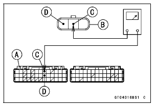

If the reading is within the standard, remove the ECU and check the wiring for continuity between harness connectors.
Special Tool - Hand Tester: 57001-1394

Disconnect the ECU and sensor connectors.
Wiring Continuity Inspection ECU Connector [A] ←→ Crankshaft Sensor Connector [B] BK lead (ECU terminal 8) [C] Y lead (ECU terminal 21) [D]
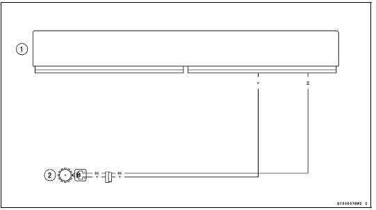
Crankshaft Sensor Circuit

1. ECU
2. Crankshaft Sensor
 Crankshaft Sensor Removal/Installation
 Rear Wheel Rotation Sensor Signal (Service Code 24)
Self-Diagnosis Procedures
NOTE
Use a fully charged battery when conducting
self-diagnosis. Otherwise, the light (LED) and symbol
do not light or blink.
Turn the ignition switch to ON.
When a problem occurs with DFI system and ignition system,
the warning indicator light (LED) [A] goes on and
FI warning symbol ...
Front Wheel Rotation Sensor Removal
NOTICE
The wheel rotation sensor should be handled carefully,
never struck sharply, as with a hammer, or allowed
to fall on a hard surface since the wheel rotation
sensor is precision made. Be careful not to get
water or mud on the wheel rotation sensor.
Do not try to disassemble or repair t ...
Rear Frame Front Removal
Remove:
Rear Frame Rear (see Rear Frame Rear Removal)
Rear Fender Front (see Rear Fender Front Removal)
Rear Footpeg Bracket Bolts [A]
Rear Footpeg Bracket [B]
Rear Frame Front Bolts [C]
Left Rear Frame Front [D]
Remove:
Rear Footpeg Bracket Bolts [A]
Rear Footpeg Bracke ...