

Rear Wheel Rotation Sensor Signal Inspection
The rear wheel rotation sensor sends the signal to the ECU through the KIBS hydraulic unit (KIBS equipped models). For other than KIBS equipped models, the signal is sent directly to the ECU.
The ECU uses the rear wheel rotation sensor signal for motorcycle speed and S-KTRC control.
The service code 24 is detected with the ECU.
Service Code b 44 (see Rear Wheel Rotation Sensor Signal Abnormal) Service Code b 45 (see Rear Wheel Rotation Sensor Wiring Inspection)
Special Tool - Hand Tester: 57001-1394
Wiring Continuity Inspection ECU Connector [A] ← → KIBS Hydraulic Unit Connector [B] R/Y lead (ECU terminal 34, KIBS Hydraulic Unit terminal 16) [C]

Wiring Continuity Inspection KIBS Hydraulic Unit Connector [A] ← → Rear Wheel Rotation Sensor Connector [B] G lead (KIBS Hydraulic Unit Connector terminal 14) [C] R lead (KIBS Hydraulic Unit Connector terminal 13) [D]
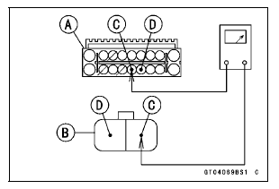
Special Tool - Hand Tester: 57001-1394
Wiring Continuity Inspection ECU Connector [A] ← → Rear Wheel Rotation Sensor Connector [B] R lead (ECU terminal 58) [C] R/Y lead (ECU terminal 34) [D]
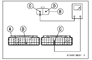
Rear Resistor Resistance (in Main Harness)
Connections:
ECU Connector [A] ← → Ground [B]
R/Y lead (ECU terminal 34) [C]
Standard: 209  231 Ω
231 Ω
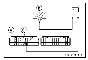
If the resistance is out of the standard, replace the main harness.
If the wiring and resistance are good, check the ECU for its ground and power supply (see ECU Power Supply Inspection in the Fuel System (DFI) chapter).
If the ground and power supply are good, replace the ECU (see ECU Removal/Installation in the Fuel System (DFI) chapter).
Wheel Rotation Sensor Circuit (KIBS Equipped Models)
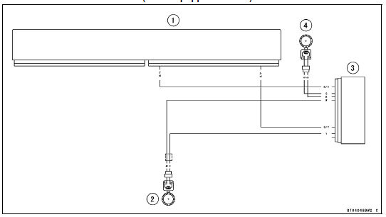
1. ECU
2. Front Wheel Rotation Sensor
3. KIBS Hydraulic Unit
4. Rear Wheel Rotation Sensor
Wheel Rotation Sensor Circuit (other than KIBS Equipped Models)
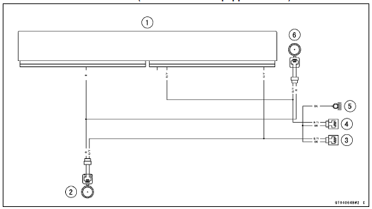
1. ECU
2. Front Wheel Rotation Sensor
3. Resistor F 220 Ω
4. Resistor R 220 Ω
5. Frame Ground 3
6. Rear Wheel Rotation Sensor
 Crankshaft Sensor Peak Voltage Inspection
Check 3-5: Warning Indicator Light (Red LED) (Oil Pressure Warning)
Inspection
Connect the leads in the same circuit as Check 3-2.
Connect the terminal [10] to the battery (–) terminal.
Check that the oil pressure warning symbol [A] and the
warning indicator light (Red LED) [B] go on.
If the indicator light does not go on, replace the meter unit.
...
Check 2-1: Speedometer Inspection
Using the suitable stand, raise the rear wheel off the
ground.
Rotate the rear wheel by hand or start the engine.
Check that the display changes speedometer.
If the display function does not work, check the following
parts.
Rear Wheel Rotation Sensor (see Wheel Rotation Sensor
Inspe ...
Tire Repair
Currently two types of repair for tubeless tires have come
into wide use. One type is called a temporary (external) repair
which can be carried out without removing the tire from
the rim, and the other type is called permanent (internal)
repair which requires tire removal. It is generally unders ...