Kawasaki Ninja Service Manual: DFI Servicing Precautions
There are a number of important precautions that should
be followed servicing the DFI system.
- This DFI system is designed to be used with a 12 V sealed
battery as its power source. Do not use any other battery
except for a 12 V sealed battery as a power source.
- Do not reverse the battery cable connections. This will
damage the ECU.
- To prevent damage to the DFI parts, do not disconnect the
battery cables or any other electrical connections when
the ignition switch is on or while the engine is running.
- Take care not to short the leads that are directly connected
to the battery positive (+) terminal to the chassis
ground.
- When charging, remove the battery from the motorcycle.
This is to prevent ECU damage by excessive voltage.
- Whenever the DFI electrical connections are to be disconnected,
first turn off the ignition switch, and disconnect
the battery (–) terminal. Do not pull the lead, only the connector.
Conversely, make sure that all the DFI electrical
connections are firmly reconnected before starting the engine.
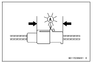
- Connect these connectors until they click [A].

- Do not turn the ignition switch to ON while any of the DFI
electrical connectors are disconnected. The ECU memorizes
service codes.
- Do not spray water on the electrical parts, DFI parts, connectors,
leads and wiring.
- If a transceiver is installed on the motorcycle, make sure
that the operation of the DFI system is not influenced by
electric wave radiated from the antenna. Check operation
of the system with the engine at idle. Locate the antenna
as far as possible away from the ECU.
- When any fuel hose is disconnected, do not turn on the
ignition switch. Otherwise, the fuel pump will operate and
fuel will spout from the fuel hose.
- Do not operate the fuel pump if the pump is completely
dry. This is to prevent pump seizure.
- Before removing the fuel system parts, blow the outer surfaces
of these parts clean with compressed air.
- When any fuel hose is disconnected, fuel may spout out
by residual pressure in the fuel line. Cover the hose joint
with a piece of clean cloth to prevent fuel spillage.
- When installing the fuel hoses, avoid sharp bending, kinking,
flattening or twisting, and run the fuel hoses with a
minimum of bending so that the fuel flow will not be obstructed.
- Run the hoses according to Cable, Wire, and Hose Routing
section in the Appendix chapter
- To prevent corrosion and deposits in the fuel system, do
not add to fuel any fuel antifreeze chemicals.
- If the motorcycle is not properly handled, the high pressure
inside the fuel line can cause fuel to leak or the hose
to burst. Remove the fuel tank (see Fuel Tank Removal)
and check the fuel hose.
Primary Fuel Hose [A]
Secondary Fuel Hose [B]

Replace the fuel hose if any fraying, cracks or bulges are
noticed.
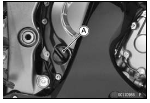
- To maintain the correct fuel/air mixture (F/A), there must
be no intake air leaks in the DFI system. Be sure to install
the oil filler plug [A] after filling the engine oil.
Torque - Oil Filler Plug: Hand-tighten

Oil Pressure Gauge, 5 kgf/cm²:
57001-125
Hand Tester:
57001-1394
Needle Adapter Set:
57001-1457
Extension Tube:
57001-1578
Fuel Pressure Gauge Adapter:
57001-1593
Fuel Hose:
57001- ...
The warning indicator light (LED) [A] is used for the FI
indicator, immobilizer indicator (immobilizer equipped models),
water temperature warning indicator and oil pressure
warning indicator.
...
Other materials:
Exploded View
11. ZX1000JD/KD
AD: Apply adhesive.
AL: Tighten the two clamp bolts alternately two times to ensure even tightening
torque.
G: Apply grease.
L: Apply a non-permanent locking agent.
Specifications
...
Fuel Pump Operating Voltage Inspection
NOTE
Be sure the battery is fully charged.
Turn the ignition switch to OFF.
Remove:
Fuel Tank Bolts (see Fuel Tank Removal)
Fuel Tank Bracket Bolts (see Fuel Tank Removal)
Disconnect the fuel pump lead connector and connect the
harness adapter [A] between these connectors as shown
i ...
Crankcase Halves Assembly
Install:
Crankshaft (see Crankshaft Installation)
Connecting Rods (see Connecting Rod Installation)
Using a cleaning fluid, clean off any oil or dirt on the mating
surface of the crankcase halves.
Apply liquid gasket to the mating surface of the lower
crankcase half as shown in the fi ...


 Special Tools and Sealant
 Troubleshooting the DFI System