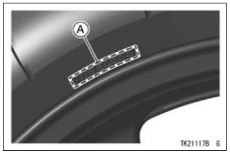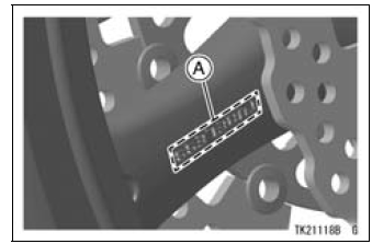

Tubeless tires are installed on the wheels of this motorcycle. The indications of “TUBELESS” on the tire side wall and the rim show that the tire and rim are specially designed for tubeless use.

A. “TUBELESS” Mark

A. “TUBELESS” Mark
The tire and rim form a leakproof unit by making airtight contacts at the tire chamfers and the rim flanges instead of using an inner tube.
| WARNING Installing a tube inside a tubeless- type tire can create excessive heat build up that can damage the tube and cause rapid deflation. The tires, rims, and air valves on this motorcycle are designed only for tubeless type wheels. The recommended standard tires, rims, and air valves must be used for replacement. Do not install tube-type tires on tubeless rims. The beads may not seat properly on the rim causing tire deflation. Do not install a tube inside a tubeless tire. Excessive heat build-up may damage the tube causing tire deflation. |
Tires
 High Speed Compression Damping Adjustment
 Payload and Tire Pressure
Fuel Pump Relay Inspection
Refer to the Relay Circuit Inspection in the Electrical System
chapter.
If the fuel pump relay is normal, check the wiring to the
fuel pump relay (see Fuel Pump Relay Circuit).
Special Tool - Hand Tester: 57001-1394
If the wiring is good, check the ECU for its ground and
power supply (se ...
What Are The Dealership’s Responsibilities?
Your Kawasaki dealer offers a wide range of services, parts, accessories, and
information on your product and on Kawasaki.
Each dealer is independently owned and operated and is responsible for the
dealership’s
operations, its repair, warranty, and service work, and its personnel.
Your dea ...
Rider’s Seat Installation
Insert the tabs on the front of the
rider’s seat into the slots in the frame
and secure the seat with mounting
bolts.
Install the seat cover and bolts.
A. Rider’s Seat
B. Tabs
C. Slots
D. Stays ...