
ECU Communication Line Inspection
When the data is not sent from the ECU to the meter unit for more than about 10 seconds, the service code 39 is displayed.
The data is sent through the CAN communication line.
The service code 39 is detected with the meter unit.
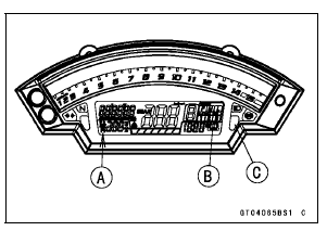
When the user mode, this communication error blinks the following items besides the FI warning symbol [A].
Power Mode and S-KTRC Symbols [B] Yellow Color LED [C]
If the CAN communication line resistance is normal, check the wiring according following procedure.
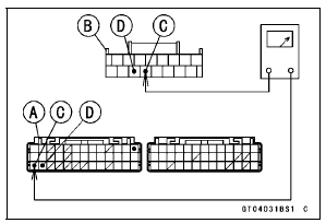
Disconnect the ECU and meter unit connectors.
Special Tool - Hand Tester: 57001-1394
Wiring Inspection ECU Connector [A] ←→ Meter Unit Connector [B] GY/BL lead (ECU terminal 27) [C] LB lead (ECU terminal 28) [D]
ECU Communication Line Circuit
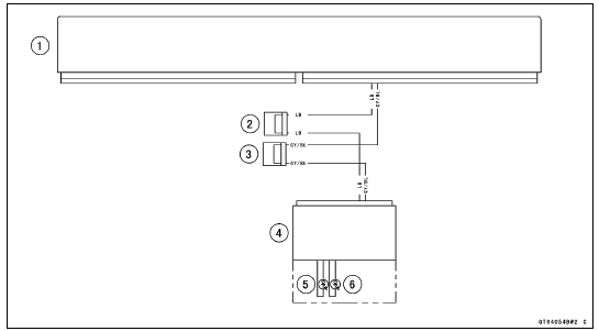
1. ECU
2. Joint Connector D
3. Joint Connector C
4. Meter Unit
5. Warning Indicator Light (LED, Yellow)
6. Warning Indicator Light (LED, Red)
 Blank Key Detection (Service Code 36, Equipped Models)
Oil Seal, Grease Seal
Do not remove pressed oil or grease seals unless removal
is necessary. Replace with new ones whenever removed.
Press new oil seals with manufacture and size marks facing
out. Make sure the seal is aligned properly when installing.
Apply specified grease to the lip of seal before installing ...
Spark Plugs
The standard spark plug is shown in
the table. The spark plugs should be
replaced in accordance with the Periodic
Maintenance Chart.
Spark plug removal should be done
only by a competent mechanic following
the instructions in the Service Manual.
Spark Plug
A. Plug Gap ...
Air Cleaner Oil Draining
A drain hose is connected to the bottom of the air cleaner
to drain water or oil accumulated in the cleaner part.
Visually check the drain hose [A] if the water or oil accumulates.
If any water or oil accumulates in the hose, remove the
plug [B] from the drain hose and drain it.
...
