
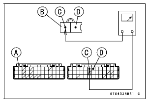
Special Tool - Hand Tester: 57001-1394
Exhaust Butterfly Valve Actuator Resistance
Connections: P lead ←→ GY lead
Standard: 5  200 Ω (for reference)
If the reading is 0 or infinity (∞) Ω, replace the exhaust butterfly valve actuator.
If the reading is in specification, remove the ECU and check the wiring for continuity between main harness connectors.
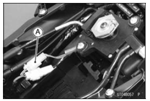
Disconnect the ECU and actuator connectors.
Wiring Inspection ECU Connector [A] ←→ Exhaust Butterfly Valve Actuator Connector [B] W/R lead (ECU terminal 45) [C] W/BL lead (ECU terminal 46) [D]
If the wiring is good, check the ECU for its ground and power supply (see ECU Power Supply Inspection in the Fuel System (DFI) chapter).
If the ground and power supply are good, replace the ECU (see ECU Removal/Installation in the Fuel System (DFI) chapter).
Exhaust Butterfly Valve Actuator Circuit
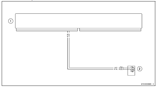
1. ECU
2. Exhaust Butterfly Valve Actuator
 Exhaust Butterfly Valve Actuator Inspection
 Air Switching Valve (Service Code 64)
Dimmer Switch
High or low beam can be selected
with the dimmer switch. When the
headlight is on high beam ( ), the
high beam indicator light goes on.
High beam.......( )
Low beam.......( )
NOTE
When the headlight is on high beam,
both headlights go on. When the
headlight is on low beam, only one
headl ...
Cylinder Compression Measurement
NOTE
Use the battery which is fully charged.
Warm up the engine thoroughly.
Stop the engine.
Remove the spark plugs (see Spark Plug Replacement in
the Periodic Maintenance chapter).
Attach the compression gauge [A] and adapter [B] firmly
into the spark plug hole.
Using the startermo ...
Valve Removal
Remove the cylinder head (see Cylinder Head Removal).
Remove the valve lifter and shim.
Mark and record the valve lifter and shim locations so they
can be installed in their original positions.
Using the valve spring compressor assembly, remove the
valve.
Special Tools - Valve ...