
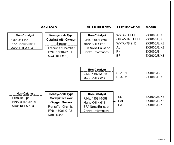
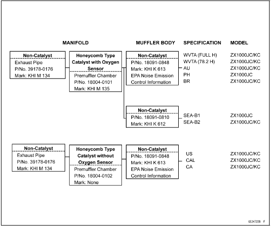
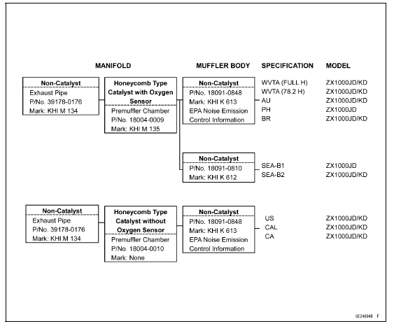
Exhaust Pipe Mark Position [A]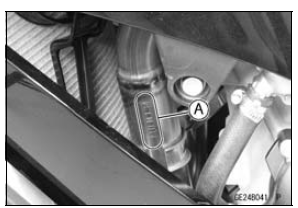
Premuffler Chamber Mark Position [A]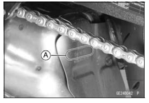
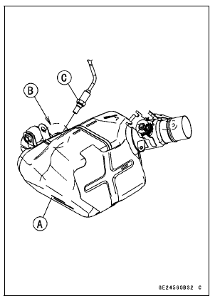
Muffler Body Mark Position [A] 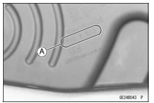
Premuffler Chamber [A] with Hole [B] for Oxygen Sensor [C]
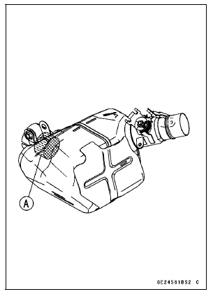
Honeycomb Type Catalyst Position [A]
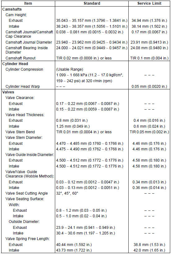
Specifications
 Exploded View
 Special Tools and Sealant
Crankshaft Sensor Peak Voltage Inspection
Refer to the Crankshaft Sensor Peak Voltage Inspection
in the Electrical System chapter.
If the reading is within the standard, remove the ECU and
check the wiring for continuity between harness connectors.
Special Tool - Hand Tester: 57001-1394
Disconnect the ECU and sensor connector ...
Check 3-4: Turn Signal Indicator Light (LED) Inspection
Connect the leads in the same circuit as Check 3-2.
Connect the terminal [5] to the battery (+) terminal.
Connect the terminal [6] to the battery (+) terminal.
Check that the turn signal indicator light (LED) [A] goes
on.
If the indicator light does not go on, replace the meter ...
Inquiries to Rider
Each rider reacts to problems in different ways, so it is important to
confirm what kind of condition
the rider is dissatisfied with.
Try to find out exactly what problem occurs under exactly what
conditions by asking the rider; knowing
this information may help you reproduce the prob ...