
Compression Gauge, 20 kgf/cm²:
57001-221 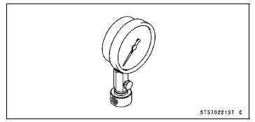
Valve Spring Compressor Assembly:
57001-241 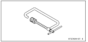
Valve Spring Compressor Adapter,
 25:
25:
57001-1019 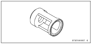
Valve Seat Cutter, 45° -  27.5:
27.5:
57001-1114 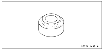
Valve Seat Cutter, 45° - 32:
32:
57001-1115 
Valve Seat Cutter, 32° -  28:
28:
57001-1119 
Valve Seat Cutter Holder Bar:
57001-1128 
Valve Seat Cutter, 32° - 33:
33:
57001-1199 
Valve Seat Cutter, 60° -  25:
25:
57001-1328 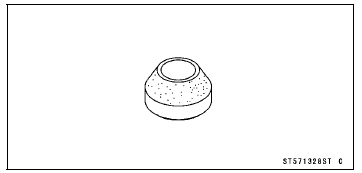
Valve Seat Cutter Holder,  4.5:
4.5:
57001-1330 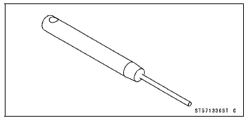
Valve Guide Arbor,  4.5:
4.5:
57001-1331 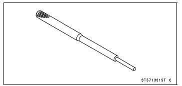
Valve Guide Reamer,  4.5:
4.5:
57001-1333 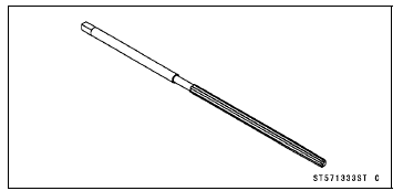
Valve Seat Cutter, 60° -  33:
33:
57001-1334 
Valve Guide Driver:
57001-1564 
Valve Spring Compressor Adapter,
24:
57001-1586 
Compression Gauge Adapter, M10 × 1.0:
57001-1601 
L-Shape Hose:
57001-1606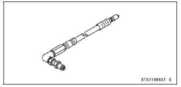
Washer:
57001-1612 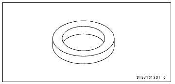
Liquid Gasket, TB1211F:
92104-0004 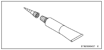
Liquid Gasket, TB1216B:
92104-1064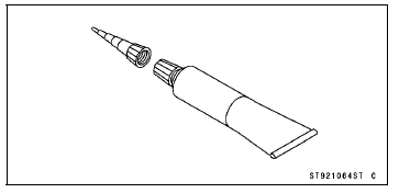
 Exhaust System Identification
 Clean Air System
Battery Installation
Visually inspect the surface of the battery container.
If any signs of cracking or electrolyte leakage from the
sides of the battery.
Put the battery into the rear fender
Install the band [A].
Connect the positive (+) cable [B] (red cap) to the positive
(+) terminal first, and then ...
Water Temperature Sensor Inspection
Remove the water temperature sensor (see Water Temperature
Sensor Removal/Installation in the Fuel System
(DFI) chapter).
Suspend the sensor [A] in a container of coolant so that
the temperature-sensing projection [C] is submerged.
Suspend an accurate thermometer [B] with temperature
...
Crankshaft Main Bearing
Insert/Journal Wear Inspection
Split the crankcase (see Crankcase Splitting).
Cut strips of plastigage to journal width.
Place a strip on each journal parallel to the crankshaft
installed in the correct position.
Tighten the crankcase bolts to the specified torque (see
Crankcase Assembly).
NOTE
Do not turn ...