
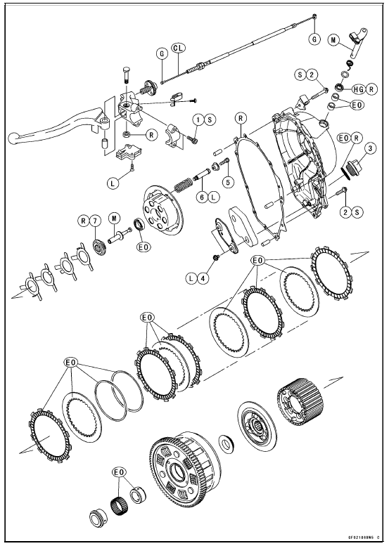
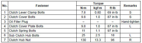
CL: Apply cable lubricant.
EO: Apply engine oil.
G: Apply grease.
HG: Apply high-temperature grease.
L: Apply a non-permanent locking agent.
M: Apply molybdenum disulfide grease.
R: Replacement Parts S: Follow the specified tightening sequence.
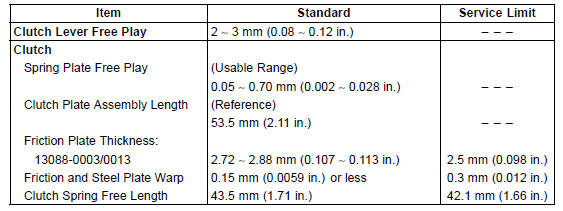
Specifications
Special Tool and Sealant
Clutch Holder:
57001-1243 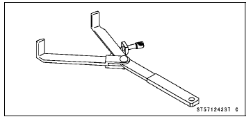
Liquid Gasket, TB1211F:
92104-0004 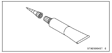
 Clutch
 Clutch Lever and Cable
Steering Damper Removal
ZX1000JC/KC
Remove:
Steering Damper Mounting Bolts (TORX Bolts) [A]
Washer [B]
Washer and Collar [C]
Steering Damper [D]
ZX1000JD/KD
Remove:
Clamp [A]
Connector [B] (Disconnect)
Steering Damper Mounting Bolts (TORX Bolts) [C]
Washer [D]
Washer and Collar [E]
Elect ...
How Do I Get Warranty Service?
If there is a problem with your vehicle within the limited warranty period,
you will
need to schedule a service appointment and provide any maintenance records to
an authorized Kawasaki dealer for inspection and diagnosis. You can go to any
Kawasaki dealer for warranty repairs. Your Kawasaki de ...
Swingarm Bearing Installation
Replace the needle bearings, ball bearing, grease seals
and circlip with new ones.
Install the needle bearings, ball bearing, grease seals and
circlip as shown in the figure.
Insert the needle bearing driver [A] into the needle bearing
[B] and press the needle bearing into the housing u ...