
S-KTRC is a highly sophisticated system based on MotoGP racing technology. Unlike the KTRC system used on the GTR1400 ABS (Concours 14 ABS in N. America), which is designed to offer rider reassurance when traversing slippery surfaces, S-KTRC, is designed to maximize forward motion, allowing riding at the edge of traction.
The quickest acceleration requires a certain amount of slip, so in order to optimize traction, S-KTRC actually allows slip. The ideal slip ratio varies according to conditions. The system looks at a number of parameters to get an accurate real-time picture of what is going on: front and rear wheel speed (slippage), engine rpm, throttle position, slippage, acceleration, etc.
Using complex analysis, the system is able to predict when traction conditions are about to become unfavorable. By acting before slippage exceeds the range for optimal traction, drops in power can be minimized resulting in ultra-smooth operation.
There are three available modes that riders can set according to preference (and skill level). Each mode is able to accommodate a range of riding conditions. Of course, engine manageability is such that riders can opt to turn the system OFF without fear of making the bike uncontrollable.
By combining the setting with the power mode, the rider can choose various riding modes to suit the road conditions and riding skill.
The system becomes functional at 5 km/h (3.1 mph) or more. If a failure occurs in the system, the warning indicator light (yellow LED) and mode indicator symbol blink to let the rider know that the system stops functioning.
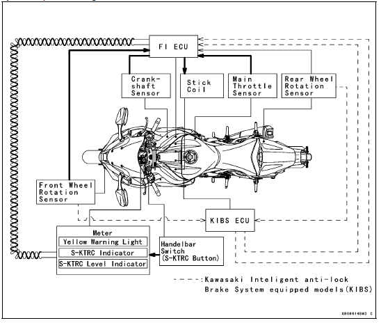
 System Components
Starter Clutch Installation
Replace the O-ring [A] with a new one and apply grease.
Apply molybdenum disulfide grease to the starter clutch
shaft [B].
Install:
Starter Clutch [C]
Spacer (Small Diameter) [D]
Spacer (Large Diameter) [E]
Starter Clutch Shaft
Starter Clutch Shaft Holder [F]
Turn the O-ring si ...
Connecting Rod Bend Inspection
Remove the connecting rod big end bearing inserts, and
reinstall the connecting rod big end cap.
Select an arbor [A] of the same diameter as the connecting
rod big end, and insert the arbor through the connecting
rod big end.
Select an arbor of the same diameter as the piston pin
and ...
Service Code Erasing
When repair has been done, warning indicator light (LED) and warning symbol
go off and service
code are not displayed.
But the service codes stored in memory of the ECU are not erased to preserve
the problem history.
In this model, the problem history can not be erased. However, the memorie ...
