
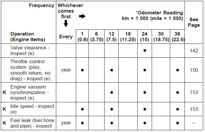
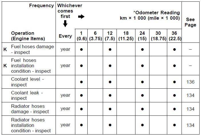
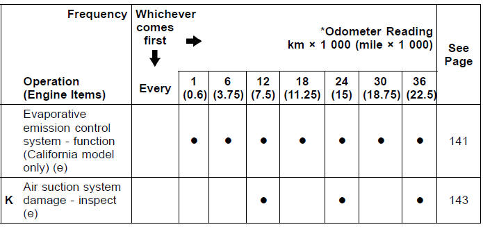
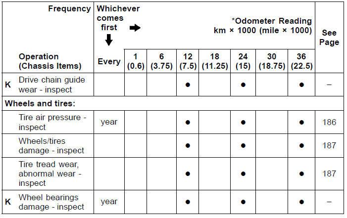
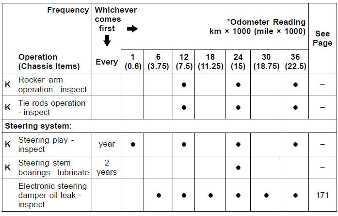
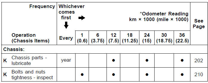
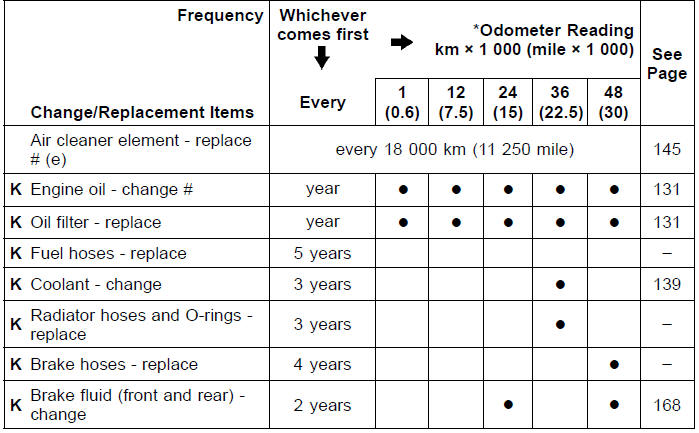
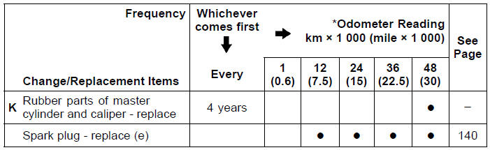
K : Should be serviced by an authorized Kawasaki dealer.
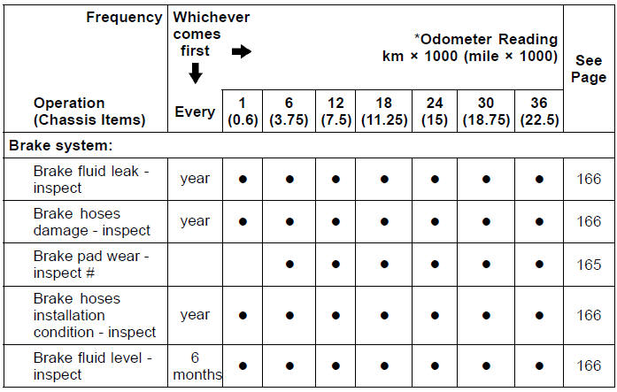
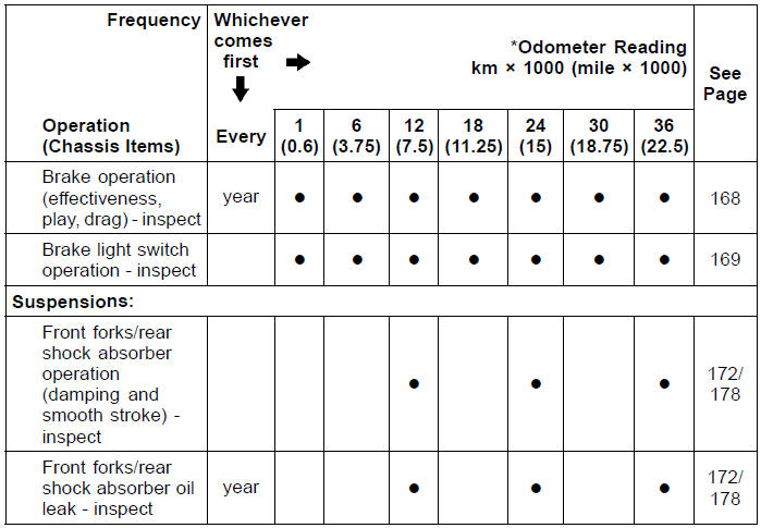
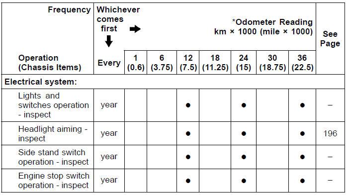
* : For higher odometer readings, repeat at the frequency interval established here.
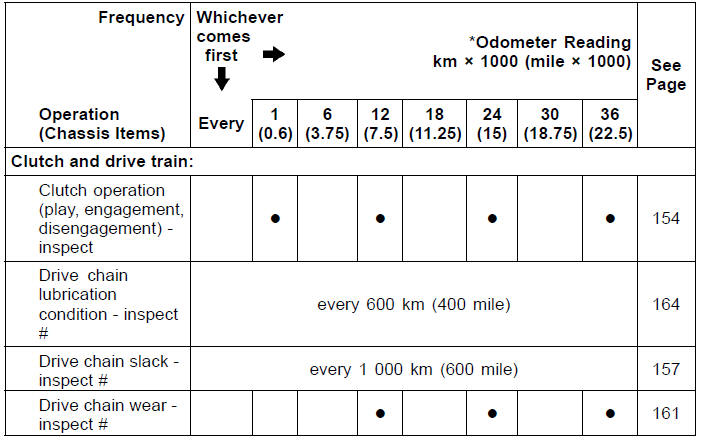
# : Service more frequently when operating in severe conditions: dusty, wet, muddy, high speed, or frequent starting/stopping.
(e): Emission Related Item
1. Periodic Inspection (Engine Related Items)
2. Periodic Inspection (Chassis Related Items)
3. Periodic Replacement
 Maintenance and adjustment
 Engine Oil
Exhaust Pipe Removal
Remove:
Radiator (see Radiator and Radiator Fan Removal in the
Cooling System chapter)
Exhaust Pipe Clamp Bolt [A] (Loosen)
Remove the exhaust pipe holder nuts [A], and pull out the
exhaust pipe [B] forward from the premuffler chamber.
...
Cable, Wire, and Hose Routing
1. Clamp (Hold the regulator/rectifier lead. Run the lead inside of the
installation hole.)
2. Clamp (Bend down the clamp, and hold the main harness and the vacuum hose
(equipped
models).)
3. Clamp (Hold the air intake solenoid valve lead (equipped models).)
4. Run the vacuum hose under ...
Moving Off
Check that the side stand is up.
Pull in the clutch lever.
Shift into 1st gear.
Open the throttle a little, and start to
let out the clutch lever very slowly.
As the clutch starts to engage, open
the throttle a littlemore, giving the engine
just enough fuel to keep it from
stallin ...