

NOTE
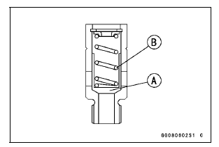
Inspect the valve in its assembled state. Disassembly and assembly may change the valve performance.
If any rough spots are found during above inspection, wash the valve clean with a high flash-point solvent and blow out any foreign particles that may be in the valve with compressed air.
| WARNING Gasoline and low flash-point solvents can be flammable and/or explosive and cause severe burns. Clean the relief valve in a well-ventilated area, and take care that there is no spark or flame anywhere near the working areas. Do not use gasoline or low flash-point solvents to clean the relief valve. |
If cleaning does not solve the problem, replace the oil pressure relief valve as an assembly. The oil pressure relief valve is precision made with no allowance for replacement of individual parts.
 Oil Pressure Relief Valve Installation
 Oil Pump
Intake Air Pressure Sensor #2 Installation
NOTE
The intake air pressure sensor #2 is the same part as
the intake air pressure sensor #1.
Installation is basically the reverse of removal.
Position the intake air pressure sensor #2 [A] between the
projections [B] on the rubber damper.
Install the rubber damper [A] on the brac ...
Master Cylinder Rubber Parts Replacement
Front Master Cylinder Disassembly
Remove the front master cylinder (see Front Master Cylinder
Removal in the Brakes chapter).
Remove the seal cover [A], circlip [B], connector [C] and
O-ring [D].
Special Tool - Inside Circlip Pliers: 57001-143
Unscrew the locknut [E] and pivot bolt ...
Front Master Cylinder Installation
Apply silicone grease to the sliding surface of the brake
lever pivot bolt.
Tighten:
Torque - Brake Lever Pivot Bolt: 1.2 N·m (0.12 kgf·m, 11
in·lb)
Brake Lever Pivot Bolt Nut: 5.9 N·m (0.60 kgf·m,
52 in·lb)
Assemble the reservoir [A] and the bracket [B] as shown
in the figu ...