
The self-diagnosis system is monitoring the following mechanisms.
DFI System and Ignition System
S-KTRC System
Immobilizer System (Equipped Models)
KIBS and ABS (Equipped Models)
ESD (Electronic Steering Damper) System
(ZX1000JD/KD)
The following warning indicator lights (LED) are used for
symbols of below table.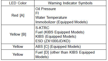
The self-diagnosis system has two modes and can be switched to another mode by operating the meter unit.
User Mode
The ECU notifies the rider of troubles in DFI system, ignition system, S-KTRC system and immobilizer system (equipped models) by lighting or blinking the warning indicator light (LED) [A], FI warning symbol [B] and immobilizer warning symbol [C] when DFI, ignition, S-KTRC and immobilizer system parts are faulty, and initiates fail-safe function. In case of serious troubles, ECU stops the injection and ignition operations.
For KIBS and ABS system (equipped models), the KIBS hydraulic unit notifies the rider of troubles in KIBS and ABS system by lighting or blinking the red warning indicator light (LED) [A], KIBS warning symbol [B] and ABS indicator light (LED) [C] when KIBS and ABS parts are faulty, and initiates fail-safe function.
For ESD system (ZX1000JD/KD), the ESD ECU notifies the rider of troubles in ESD system by lighting the yellow warning indicator light (LED) and ESD warning symbol [D] when ESD parts are faulty, and initiates fail-safe function.
Dealer Mode
The LCD (Liquid Crystal Display) displays the service code(s) [A] to show the problem(s) which the above system has at the moment of diagnosis.
 Self-Diagnosis
 Self-Diagnosis Procedures
Brake Light Switches
When either the front or rear brake is
applied, the brake light goes on. The
front brake light switch requires no adjustment,
but the rear brake light switch
should be adjusted in accordance with
the Periodic Maintenance Chart.
Inspection
Turn the ignition key to “ON”.
The brake ligh ...
Intake Air Temperature Meter
Intake air temperature meter indicates
temperature of the air in the air
cleaner case.
The “Intake Air” is displayed if the intake
air temperature meter is selected.
A. Intake Air Temperature Meter
B. “Intake Air”
NOTE
The intake air temperature meter
shift to the coolant temp ...
Multifunction Display
The multifunction display indicates
the following modes.
Odometer
Trip meter A
Trip meter B
Current Mileage
Average Mileage
Fuel Consumption
Stop Watch
These display modes can be shifted
by pushing the upper button.
NOTE
The “FUEL” warning can be indicated
if the ...