
NOTE
Use a fully charged battery when conducting self-diagnosis. Otherwise, the light (LED) and symbol do not light or blink.
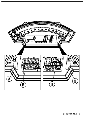
When a problem occurs with DFI system and ignition system, the warning indicator light (LED) [A] goes on and FI warning symbol [B] are displayed on the LCD (Liquid Crystal Display) to alert the rider.
For models equipped with S-KTRC system, the warning indicator light (LED) [C] goes on and S-KTRC symbols [D] are alternately displayed on the LCD, when a problem occurs in the system.
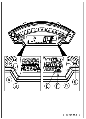
The service code of the KIBS and ABS adds “b” at the left side of the code.
The service code of the ESD adds “E” at the left side of the code.
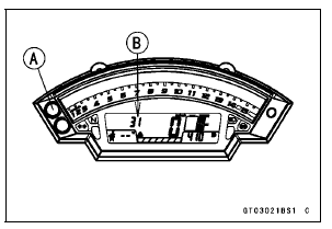
When the service code is displayed on the LCD, push the upper button and lower buttons for more than two seconds.
The display will return to the odometer.
When the ignition switch is turned to OFF.
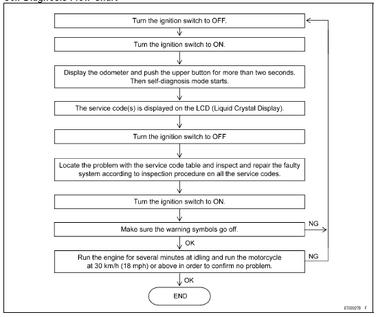
Self-Diagnosis Flow Chart
 Self-Diagnosis Outline
 Service Code Reading
Periodic Maintenance Chart
The scheduled maintenance must be done in accordance with this chart to keep
the motorcycle in
good running condition. The initial maintenance is vitally important and must
not be neglected.
Periodic Inspection
#: Service more frequently when operating in severe conditions; dusty, ...
Subthrottle Sensor Input Voltage Inspection
NOTE
Be sure the battery is fully charged.
Turn the ignition switch to OFF.
Remove the air cleaner housing (see Air Cleaner Housing
Removal in the Fuel System (DFI) chapter)
Disconnect the subthrottle sensor connector and connect
the harness adapter [A] between these connectors.
Spec ...
Coupling Bearing Installation
Replace the bearing with a new one.
Press in the bearing [A] until it is bottomed.
Special Tool - Bearing Driver Set [B]: 57001-1129
Pack the bearing with high-temperature grease.
Replace the circlip with a new one.
Special Tool - Inside Circlip Pliers: 57001-143
Replace the grease se ...