
There are three types of alternator failures: short, open (wire burned out), or loss in rotor magnetism. A short or open in one of the coil wires will result in either a low output, or no output at all. A loss in rotor magnetism, which may be caused by dropping or hitting the alternator, by leaving it near an electromagnetic field, or just by aging, will result in low output.
Turn the ignition switch to OFF.
Remove the left upper inner fairing (see Upper Inner Fairing Removal in the Frame chapter).
Disconnect the alternator lead connector [A].
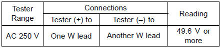
Connect the hand tester as shown in the table 1.
Special Tool - Hand Tester: 57001-1394
Start the engine.
Run it at the rpm given in the table 1.
Note the voltage readings (total 3 measurements).
Table 1 Alternator Output Voltage at 4 000 r/min (rpm)
If the output voltage shows the value in the table, the alternator operates properly. The regulator/rectifier is damaged.
If the output voltage shows a much lower reading than that given in the table, stop the engine and inspect the stator coil resistance.
Stop the engine.
Connect the hand tester as shown in the table 2.
Special Tool - Hand Tester: 57001-1394
Table 2 Stator Coil Resistance at 20┬░C (68┬░F)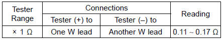
If there is more resistance than shown in the table, or no hand tester reading (infinity) for any two leads, the stator has an open lead and must be replaced. Much less than this resistance means the stator is shorted, and must be replaced.
Any hand tester reading less than infinity (∞) indicates a short, necessitating stator replacement.
If the stator coil has normal resistance, but the voltage check showed the alternator to be defective; then the rotor magnets have probably weakened, and the rotor must be replaced.
 Charging Voltage Inspection
 Regulator/Rectifier Inspection
Fuel Hose Replacement
Remove the fuel tank (see Fuel Tank Removal in the Fuel
System (DFI) chapter).
WARNINGFuel is flammable and explosive under
certain conditions
and can cause severe burns. Be prepared
for fuel spillage; any spilled fuel must be completely
wiped up immediately. When the fue ...
For Primary Fuel Injectors
Remove the air cleaner housing (see Air Cleaner Housing
Removal).
Disconnect the primary fuel injector connector [A].
Connect a digital meter to the terminals in each primary
fuel injector [A].
Measure the primary fuel injector resistance.
Primary Fuel Injector Resistance ...
Intake Air Pressure Sensor #1 Removal
NOTICE
Never drop the intake air pressure sensor #1 especially
on a hard surface. Such a shock to the sensor
can damage it.
Remove:
Air Cleaner Housing (see Air Cleaner Housing Removal
in the Fuel System (DFI) chapter)
Intake Air Pressure Sensor #1 Connector [A]
Remove the intake air ...