
The compression damping force adjuster and the rebound damping force adjuster are located on top of each front fork leg.
NOTICE
Do not force to turn the rebound and compression damping force adjuster from the fully seated position, or the adjusting mechanism may be damaged.
A. Compression Damping Force Adjuster (COM)
B. Rebound Damping Force Adjuster (TEN)
C. Screwdriver
Compression Damping Force Setting and Rebound Damping Force Setting
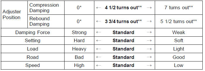
*: This position is the fully seated position (turned fully clockwise).
**: Out from the fully seated position (turned fully clockwise). This adjustment range may not exactly match the number shown in the table due to small tolerance of production.
The standard front fork setting positions are as follows:
Standard Setting Position (Front Fork)
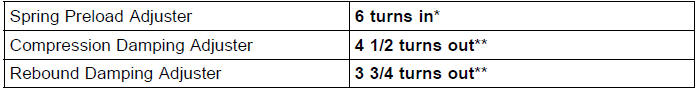
*: In from the fully seated position (turned fully counterclockwise) **: Out from the fully seated position (turned fully clockwise)
 Spring Preload Adjustment
 Rear Shock Absorber
Fuel Pump Relay Inspection
Refer to the Relay Circuit Inspection in the Electrical System
chapter.
If the fuel pump relay is normal, check the wiring to the
fuel pump relay (see Fuel Pump Relay Circuit).
Special Tool - Hand Tester: 57001-1394
If the wiring is good, check the ECU for its ground and
power supply (se ...
Intake Air Temperature Sensor Output Voltage Inspection
NOTE
Be sure the battery is fully charged.
Turn the ignition switch to OFF.
Remove the fuel tank (see Fuel Tank Removal in the Fuel
System (DFI) chapter).
Disconnect the intake air temperature sensor connector
and connect the measuring adapter [A] between these
connectors as shown in ...
Throttle Body Assy Holder Installation
Be sure to install the new O-rings [A].
Using a high flash-point solvent, clean off any oil or dirt
that may be on the silicone sealant coating area. Dry
them with a clean cloth.
Apply silicone sealant to any two positions of the new O
-ring.
Sealant - Liquid Gasket, TB1211F: 92104-0 ...