
The spring preload adjuster is located at the lower end of each front fork leg and can be adjusted.
A. Spring Preload Adjuster
B. Hexagon Wrench
Spring Preload Setting
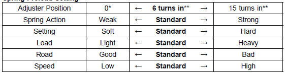
*: This position is the fully seated position (turned fully counterclockwise).
**: In from the fully seated position (turned fully counterclockwise). This adjustment range may not exactly match the number shown in the table due to small tolerance of production.
 Front Fork Inspection
 Compression Damping Force Adjuster and Rebound
Damping Force Adjuster Adjustment
Compression Damping Force Adjuster and Rebound
Damping Force Adjuster AdjustmentCamshaft Chain Tensioner Installation
Replace the O-ring [A] with a new one.
Apply grease to the new O-ring.
Release the stopper [B] and push the push rod [C] into the
interior of the tensioner body [D] so that the position of the
push rod is 3 or 4 notches [E] as shown in the figure.
Install the tensioner body so that the ...
CAN Communication (Transmission)/CAN Bus OFF Monitor Inspection (Service Code
b 57) CAN Communication (Reception) Monitor Inspection (Service Code b 58)
Remove:
Seat (see Seat Removal in the Frame chapter)
Immobilizer (Equipped Models)/Kawasaki Diagnostic
System Connector Cap [A]
Measure the CAN communication line resistance.
Immobilizer (Equipped Models)/Kawasaki Diagnostic
System Connector [A]
GY/BL Terminal [B]
LB Ter ...
Gear Position Switch Installation
Securely place the springs [A] and pins [B] into the holes
[C] of the shift drum.
Apply grease to the new O-ring [D].
Install the gear position switch [E].
Apply a non-permanent locking agent to the threads of
the gear position switch screws [F].
Tighten:
Torque - Gear Position Swit ...