
NOTE
Do not move the connecting rod and crankshaft during clearance measurement.
Remove the connecting rod big end again, measure each clearance between the bearing insert and crankpin [A] using plastigage (press gauge) [B].
NOTICE
After measurement, replace the connecting rod bolts and nuts.
Connecting Rod Big End Bearing Insert/Crankpin Clearance
Standard: 0.030  0.060 mm
(0.0012  0.0024 in.)
Service Limit: 0.10 mm (0.0039 in.)
If the clearance is within the standard, no bearing replacement is required.
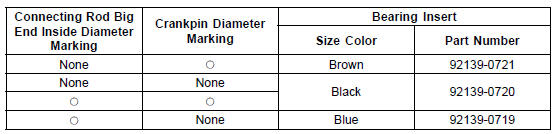
If the clearance is between 0.061 mm (0.0024 in.) and the service limit (0.10 mm, 0.0039 in.), replace the bearing inserts [A] with inserts painted blue [B]. Check insert/ crankpin clearance with the plastigage. The clearance may exceed the standard slightly, but it must not be less than the minimum in order to avoid bearing seizure.
If the clearance exceeds the service limit, measure the diameter of the crankpins.
Crankpin Diameter
Standard: 34.484  34.500 mm
(1.3576  1.3583 in.)
Service Limit: 34.47 mm (1.3571 in.)
Crankpin Diameter Marks
None 34.484  34.492 mm (1.3576
1.3580 in.)
 34.493
 34.500 mm (1.3580
 1.3583 in.)
 : Crankpin Diameter Marks (“” or
No Mark)
NOTE
The mark already on the big end should almost coincide with the measurement.
Connecting Rod Big End Inside Diameter Marks
None 37.500  37.508 mm
(1.4764  1.4767 in.)
 37.509
 37.516 mm (1.4767
 1.4770 in.)
Big End Cap [A] Connecting Rod [B] Weight Mark, Alphabet [C] Diameter Mark [D] (“” or No Mark)
Size Color [B]
 Connecting Rod Big End Side Clearance Inspection
 Crankshaft Side Clearance Inspection
Battery Removal
Turn off the ignition switch.
Remove the front seat (see Front Seat Removal in the
Frame chapter).
Slide the red cap [A].
Disconnect the negative (–) cable [B] and then positive
(+) cable [C].
NOTICE
Be sure to disconnect the negative (–) cable first.
Remove the band [D] ...
Refreshing Charge
Remove the battery (see Battery Removal).
Do refresh charge by following method according to the
battery terminal voltage.
WARNINGThis battery is sealed type. Charge with
current and
time as stated below.
Terminal Voltage: 12.0 12.7
V
Standard Charge (see following ...
Oxygen Sensor - not activated (Service Code 33, Equipped Models)
Oxygen Sensor Removal/Installation
Refer to the Oxygen Sensor Removal/Installation
(Equipped Models) in the Electrical System chapter.
Oxygen Sensor Inspection
Remove:
Fuel Tank (see Fuel Tank Removal in the Fuel System
(DFI) chapter)
Oxygen Sensor Lead Connector [A]
Connect t ...