
ESD ECU Communication Line Inspection
When the data (for status of ESD system) is not sent from the ESD ECU to the meter unit and ECU, the service code 3C is displayed.
The data is sent through the CAN communication line.
The service code 3C is detected with the meter unit.
The FI symbol does not appear in this error code.
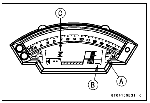
When the service code 3C is detected, the yellow warning indicator light (LED) [A] goes on, and the ESD warning symbol [B] and code of 3C [C] displayed on the LCD.
Special Tool - Hand Tester: 57001-1394
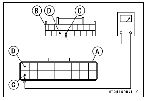
Wiring Inspection ESD ECU Connector [A] ←→ Meter Unit Connector [B] GY/BL lead (ESD ECU terminal 10) [C] LB lead (ESD ECU terminal 1) [D]
If the wiring is good, replace the ESD ECU (see ESD ECU Removal/Installation in the Steering chapter).
 Air Intake Solenoid Valve (Service Code 2d, Equipped Models)
 ESD (Electronic Steering Damper) Actuator Error (Service Code E2E,
ZX1000JD/KD)
ESD (Electronic Steering Damper) Actuator Error (Service Code E2E,
ZX1000JD/KD)Exploded View
14. Thermostat
15. Frame No. JKAZXT00JJA003074
or JKAZXCJ1
BA003074
G: Apply grease.
HG: Apply high-temperature grease.
L: Apply a non-permanent locking agent.
R: Replacement Parts
S: Follow the specified tightening sequence.
W: Apply water.
1. US, CA and CAL Models
2. Fra ...
Brake Disc Warp Inspection
Raise the wheel off the ground with the jack.
Special Tools - Jack: 57001-1238
Jack Attachment: 57001-1608
For front disc inspection, turn the handlebar fully to one
side.
Set up a dial gauge against the disc [A] as shown in
the figure and measure disc runout, while turning [B] the
...
Air Cleaner Housing Installation
For ZX1000JD/KD, be sure to install the pad [A].
Install the clamp bolt heads [A] inside as shown in the
figure.
Install the air cleaner housing on the throttle body assy.
Push in the ducts [B] touch the stoppers [C] of the throttle
body.
Be sure the hoses are routed correctly ...