
Sidestand Switch Operation
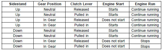
If the sidestand switch operation does not work, inspect or replace the following parts.
Battery (see Charging Condition Inspection in the Electrical System chapter)
Main Fuse 30 A (see Fuse Inspection in the Electrical System chapter) Ignition Fuse 15 A (see Fuse Inspection in the Electrical System chapter) Ignition Switch (see Switch Inspection in the Electrical System chapter) Sidestand Switch (see Switch Inspection in the Electrical System chapter) Engine Stop Switch (see Switch Inspection in the Electrical System chapter) Starter Button (see Switch Inspection in the Electrical System chapter) Gear Position Switch (see Gear Position Switch Inspection in the Electrical System chapter) Starter Lockout Switch (see Switch Inspection in the Electrical System chapter) Starter Relay (see Starter Relay Inspection in the Electrical System chapter) Relay Box (see Relay Circuit Inspection in the Electrical System chapter) Starter Circuit Relay (see Relay Circuit Inspection in the Electrical System chapter) Harness (see Wiring Inspection in the Electrical System chapter)
If the all parts are good condition, replace the ECU (see ECU Removal/Installation in the Fuel System (DFI) chapter).
 Headlight Aiming Adjustment
 Engine Stop Switch Operation Inspection
Cam Wear Inspection
Remove the camshafts (see Camshaft Removal).
Measure the height [A] of each cam with a micrometer.
If the cams are worn down past the service limit, replace
the camshaft.
Cam Height
Standard:
Exhaust 35.043 35.157 mm
(1.3796 1.3841 in.)
Intake 38.243 38.357 mm
(1.5056 1.5101 in. ...
Starter Clutch Assembly
Install the one-way clutch [A] to the driven gear.
Face the circlip side of the one-way clutch to inside.
Install the new snap ring [B] to the one-way clutch.
Install the drive gear [C] while turn it counterclockwise [D].
Apply molybdenum disulfide oil solution to the needle
bearing ...
What Are The Dealership’s Responsibilities?
Your Kawasaki dealer offers a wide range of services, parts, accessories, and
information on your product and on Kawasaki.
Each dealer is independently owned and operated and is responsible for the
dealership’s
operations, its repair, warranty, and service work, and its personnel.
Your dea ...