
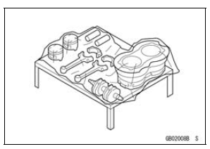
After all the parts including subassembly parts have been cleaned, store the parts in a clean area. Put a clean cloth or plastic sheet over the parts to protect from any foreign materials that may collect before re-assembly.
Inspection
Reuse of worn or damaged parts may lead to serious accident.
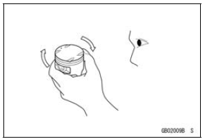
Visually inspect removed parts for corrosion, discoloration, or other damage. Refer to the appropriate sections of this manual for service limits on individual parts. Replace the parts if any damage has been found or if the part is beyond its service limit.
 Cleaning Vehicle before Disassembly
 Replacement Parts
Crankshaft Removal
Split the crankcase (see Crankcase Splitting).
Remove:
Connecting Rod Big End Nuts [A]
Connecting Rod Big End Caps [B]
NOTE
Mark and record the locations of the connecting rods
and their big end caps so that they can be reassembled
in their original positions.
Remove the crank ...
Rear Caliper Holder Shaft Wear
The caliper body must slide smoothly on the caliper holder
shafts [A]. If the body does not slide smoothly, one pad will
wear more than the other, pad wear will increase, and constant
drag on the disc will raise brake and brake fluid temperature.
Check to see that the caliper holder shafts ar ...
Lubrication
Lubrication is necessary after riding
through rain or on wet roads, or any
time that the chain appears dry.
Use a lubricant for sealed chains to
prevent deterioration of chain seals. If
the chain is especially dirty, clean it
using a cleaner for sealed chains following
the instructions suppli ...