
NOTE
Mark and record the locations of the valve lifters and shims so that they can be reinstalled in their original positions.
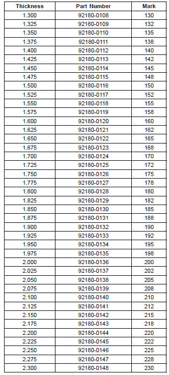
a + b – c = d
[a] Present Shim Thickness
[b] Measured Valve Clearance
[c] Specified Valve Clearance (Mean Value = 0.195 mm (Exhaust), 0.185 mm (Intake))
[d] Replace Shim Thickness
Example (Exhaust): 1.600 + 0.28 – 0.195 = 1.685 mm
Exchange the shim for the 1.675 size shim.
Adjustment Shims
NOTICE
Be sure to remeasure the clearance after selecting a shim. The clearance can be out of the specified range because of the shim tolerance.
If there is no valve clearance, use a shim that is a few sizes smaller, and remeasure the valve clearance.
NOTICE
Do not put shim stock under the shim. This may cause the shim to pop out at high rpm, causing extensive engine damage.
Do not grind the shim. Thismay cause it to fracture, causing extensive engine damage.
 Valve Clearance Inspection
 Air Suction System Damage Inspection
KIBS Troubleshooting Outline
When an abnormality in the system occurs, the ABS indicator
light (LED) and KIBS indicator light (LED) light up and
the KIBS warning symbol are displayed on the LCD (Liquid
Crystal Display) to alert the rider. In addition, the nature of
the fault is stored in the memory of the KIBS hydraulic uni ...
Water Pump Impeller Disassembly/Assembly
Remove the water pump impeller (see Oil Pump Removal
in the Engine Lubrication System chapter).
The sealing seat and rubber seal may be removed easily
by hand.
Apply coolant around the surfaces of the rubber seal and
sealing seat.
Install the rubber seal [A] and sealing seat [B] into ...
Seat Cover Installation
Installation is the reverse of removal. Note the following.
When installing the pad [A], install it along the corner [B]
as shown in the figure.
When installing the pad [C], align the ends [D], along the
corner [E], and wrap [F] the upper edge of the seat cover.
Install the damper [A] ...