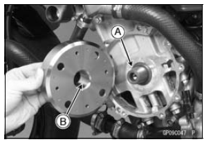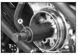

Crankshaft Tapered Portion [A] Alternator Rotor Tapered Portion [B]


NOTE
Confirm the alternator rotor fit or not to the crankshaft before tightening it with specified torque.
Special Tool - Flywheel Puller Assembly, M38 × 1.5/M35 × 1.5: 57001-1405

If the rotor is not pulled out with 20 N·m (2.0 kgf·m, 15 ft·lb) of drawing torque, it is installed correctly.
If the rotor is pulled out with under 20 N·m (2.0 kgf·m, 15 ft·lb) of drawing torque, clean off any oil dirt or flaw of the crankshaft and rotor tapered portion, and dry them with a clean cloth. Then, confirm that it is not pulled out with above torque.

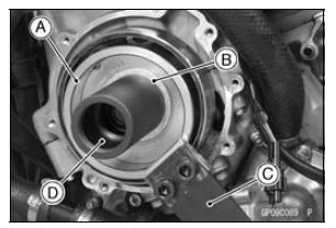
Special Tools - Grip [C]: 57001-1591 Rotor Holder: 57001-1666 Flywheel Puller Assembly, M38 × 1.5/M35 × 1.5 [D]: 57001-1405 Rotor Holder Attachment: 57001-1689 Torque - Alternator Rotor Bolt: 155 N·m (15.8 kgf·m, 114 ft·lb)
 Alternator Rotor Removal
 Charging Voltage Inspection
Air Cleaner Element Replacement
NOTE
In dusty areas, the element should be replaced more
frequently than the recommended interval.
WARNINGIf dirt or dust is allowed to pass through
into the
throttle body assy, the throttle may become stuck,
possibly causing accident. Replace the air cleaner
element according ...
Oxygen Sensor Heater Resistance Inspection
Turn the ignition switch to OFF.
Remove the fuel tank (see Fuel Tank Removal in the Fuel
System (DFI) chapter).
Disconnect the oxygen sensor lead connector [A].
Connect a digital meter [A] to the terminals in the oxygen
sensor lead connector [B].
Measure the oxygen sensor heat ...
Stopping the Motorcycle in an Emergency
Your Kawasaki Motorcycle has been
designed and manufactured to provide
you optimum safety and convenience.
However, in order to fully benefit
from Kawasaki’s safety engineering
and craftsmanship, it is essential that
you, the owner and operator, properly
maintain your motorcycle and becom ...