
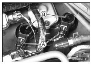
First, turn the stick coil by 90 degrees, and then pull it out by twisting the coil head to the left and right while holding it securely by hand.
NOTICE
Do not pry the connector part of the coil while removing the coil.
 Timing Rotor Installation
 Stick Coil Installation
Hub Bearing Inspection
Since the hub bearings are made to extremely close tolerances,
the clearance can not normally be measured.
NOTE
Do not remove any bearings for inspection. If any bearings
are removed, they will need to be replaced with
new ones.
Turn each bearing in the hub back and forth [A] while
checki ...
Sprocket Wear Inspection
Visually inspect the engine and rear sprocket teeth for
wear and damage.
If the teeth are worn as illustrated, replace the sprocket,
and inspect the drive chain wear (see Drive Chain Wear
Inspection in the Periodic Maintenance chapter).
Worn Tooth (Engine Sprocket) [A]
Worn Tooth (Rear ...
Oil Level Inspection
If the oil has just been changed, start
the engine and run it for severalminutes
at idle speed. This fills the oil
filter with oil. Stop the engine, then
wait several minutes until the oil settles.
NOTICE
Racing the engine before the oil
reaches every part can cause engine
seizure.
...