
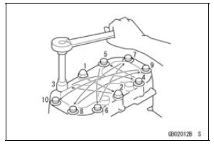
Generally, when installing a part with several bolts, nuts, or screws, start them all in their holes and tighten them to a snug fit. Then tighten them according to the specified sequence to prevent case warpage or deformation which can lead to malfunction. Conversely when loosening the bolts, nuts, or screws, first loosen all of them by about a quarter turn and then remove them. If the specified tightening sequence is not indicated, tighten the fasteners alternating diagonally.
Tightening Torque
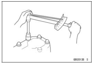
Incorrect torque applied to a bolt, nut, or screw may lead to serious damage. Tighten fasteners to the specified torque using a good quality torque wrench.
 Replacement Parts
 Force
ForceEngine Sprocket Removal
Remove:
Engine Sprocket Cover Bolts [A]
Engine Sprocket Cover [B]
Flatten out the bended washer [A].
Remove the engine sprocket nut [B] and washer.
NOTE
When loosening the engine sprocket nut, hold the rear
brake on.
Raise the rear wheel off the ground with the stand. ...
Camshaft Chain Tensioner Installation
Replace the O-ring [A] with a new one.
Apply grease to the new O-ring.
Release the stopper [B] and push the push rod [C] into the
interior of the tensioner body [D] so that the position of the
push rod is 3 or 4 notches [E] as shown in the figure.
Install the tensioner body so that the ...
Hub Bearing Installation
Before installing the hub bearings, blow any dirt or foreign
particles out of the hub with compressed air to prevent
contamination of the bearings.
Replace the bearings with new ones.
Install the bearings by using the bearing driver set which
does not contact the bearing inner race.
...