
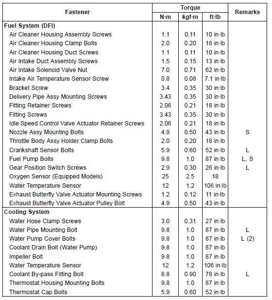
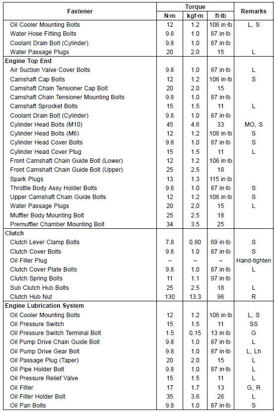
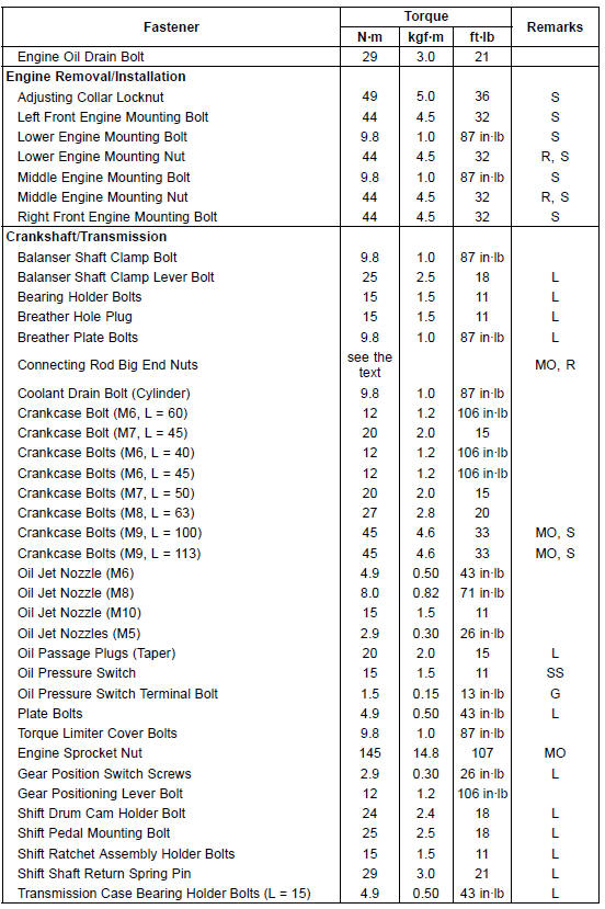
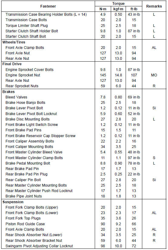
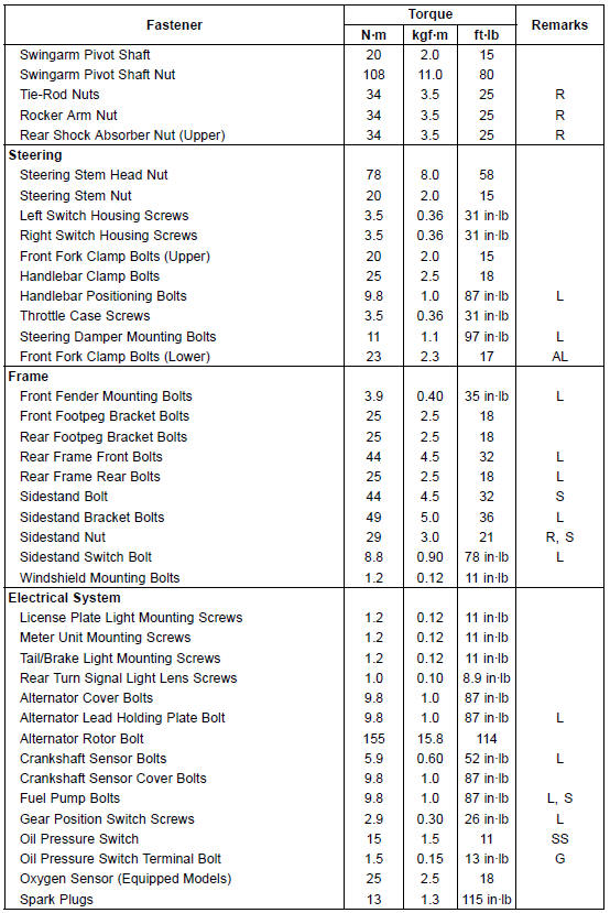
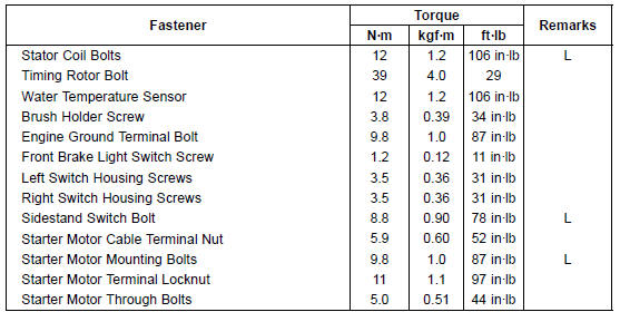
The following tables list the tightening torque for the major fasteners requiring use of a non-permanent locking agent or silicone sealant etc.
Letters used in the “Remarks” column mean: AL: Tighten the two clamp bolts alternately two times to ensure even tightening torque.
G: Apply grease.
L: Apply a non-permanent locking agent.
Lh: Left-hand Threads
MO: Apply molybdenum disulfide oil solution.
(mixture of the engine oil and molybdenum disulfide grease in a weight ratio 10:1)
R: Replacement Parts
S: Follow the specified tightening sequence.
Si: Apply silicone grease (ex. PBC grease).
SS: Apply silicone sealant.
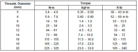
The table below, relating tightening torque to thread diameter, lists the basic torque for the bolts and nuts. Use this table for only the bolts and nuts which do not require a specific torque value. All of the values are for use with dry solvent-cleaned threads.
Basic Torque for General Fasteners
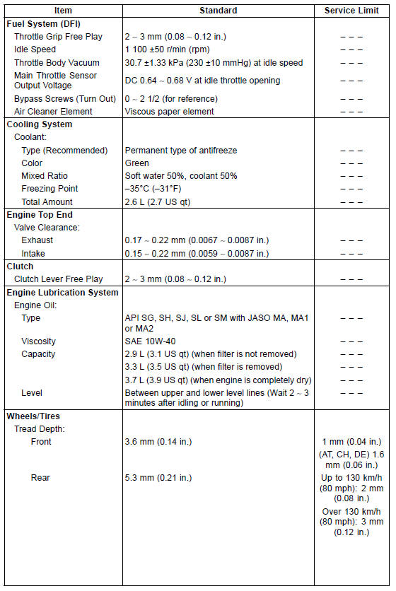
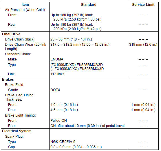
Specifications
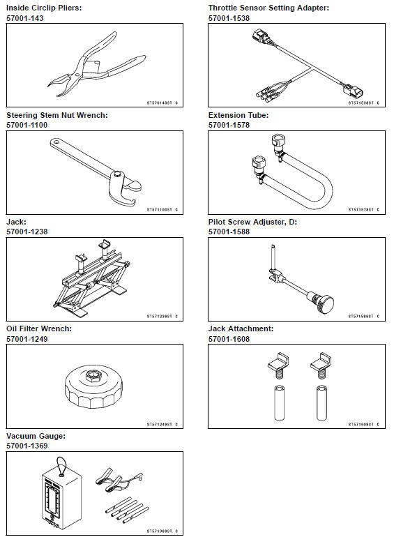
Special Tools
 Periodic Maintenance Chart
Air Cleaner
A clogged air cleaner restricts the engine’s
air intake, increasing fuel consumption,
reducing engine power, and
causing spark plug fouling.
This motorcycle’s air cleaner element
consists of a wet paper filter, which cannot
be cleaned.
The air cleaner element must be replaced
in acco ...
Multifunction Meter
A. Multifunction Display
Odometer
Trip Meters
Current Mileage
Average Mileage
Fuel consumption
Stop Watch
B. Speedometer
C. Gear Position Indicator
D. Power Mode Indicator
E. S-KTRC Mode Indicator
F. Warning Symbols
G. Lap Counter/Coolant /
Intake Air Temperature
Meter
...
Exhaust Butterfly Valve Actuator Removal
NOTICE
Never drop the exhaust butterfly valve actuator especially
on a hard surface. Such a shock to the actuator
can damage it.
Remove:
Front Seat (see Front Seat Removal in the Frame chapter)
Clamp [A]
Screws [B] and Washers
Slide the covers [A] and loosen the lock nuts [B] ...
