
The scheduled maintenance must be done in accordance with this chart to keep the motorcycle in good running condition. The initial maintenance is vitally important and must not be neglected.
Periodic Inspection
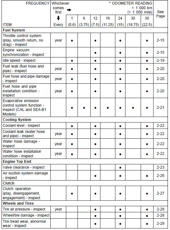
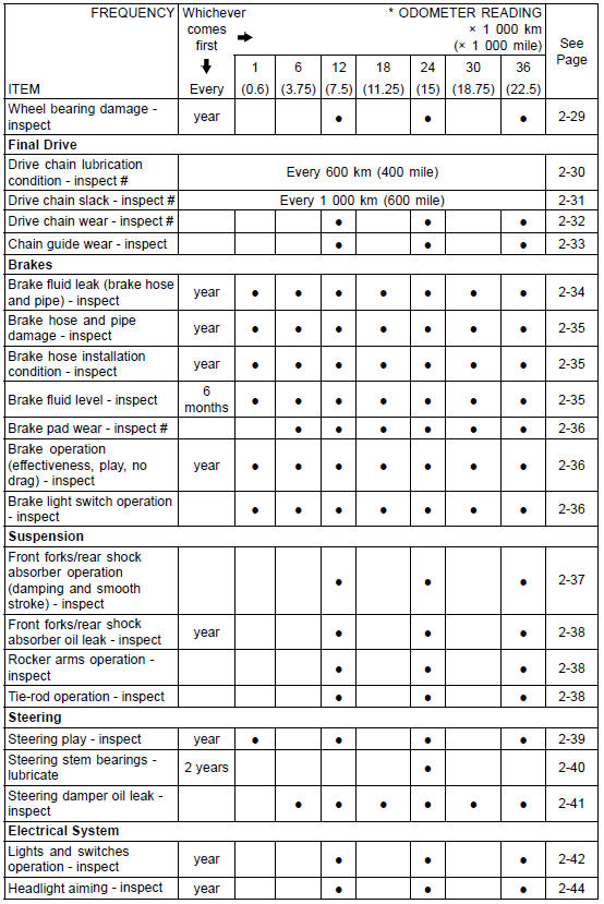
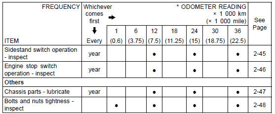
#: Service more frequently when operating in severe conditions; dusty, wet, muddy, high speed or frequent starting/stopping.
*: For higher odometer readings, repeat at the frequency interval established here.
Periodic Replacement Parts
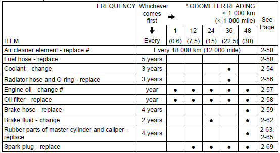
#: Service more frequently when operating in severe conditions; dusty, wet, muddy, high speed or frequent starting/stopping.
*: For higher odometer readings, repeat at the frequency interval established here.
 Torque and Locking Agent
KIBS Warning Indicator Light (For models equipped
with KIBS)
The yellow warning indicator light in
the meter unit functions as the KIBS
warning indicator light. The yellow
warning indicator light and warning
symbol “KIBS� go on if there is a malfunction
in the KIBS system. When the
warning light is on, the KIBS system
stops functioning. However, th ...
Valve Guide Removal
Remove:
Valve (see Valve Removal)
Oil Seal
Spring Seat
Heat the area around the valve guide to 120
150°C (248
302°F), and hammer lightly on
the valve guide arbor [A]
to remove the guide from the top of the head.
NOTICE
Do not heat the cylinder head with a torch. This ...
Storage of Removed Parts
After all the parts including subassembly parts have been
cleaned, store the parts in a clean area. Put a clean cloth
or plastic sheet over the parts to protect from any foreign
materials that may collect before re-assembly.
Inspection
Reuse of worn or damaged parts may lead to serious acci ...
