
Turn Signal Relay [A] Turn Signal Lights [B] 12 V Battery [C]
If the lights do not blink as specified, replace the turn signal relay.
Testing Turn Signal Relay 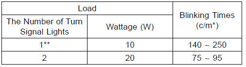
(*): Cycle(s) per minute
(**): Corrected to “one light burned out”.
Turn Signal Light Circuit
1. Ignition Switch
2. Joint Connector A
3. Rear Right Turn Signal Light 12 V 10 W
4. Rear Left Turn Signal Light 12 V 10 W
5. Joint Connector B
6. Battery
7. Main Fuse 30 A
8. Frame Ground
9. Turn Signal Relay
10. Turn Signal Switch
11. Turn Signal Relay Fuse 10 A
12. Fuse Box 1
13. Front Left Turn Signal Light (LED)
14. Front Right Turn Signal Light (LED)
15. Turn Signal Indicator Light (LED)
 Rear Turn Signal Light Bulb Replacement
 Air Switching Valve
Lights and Switches Operation Inspection
First Step
Set the gear position in the neutral position.
Turn the ignition switch to ON.
The following lights should go on according to below table.
If the following light does not go on, inspect the meter
unit (see Meter Unit Inspection in the Electrical System
chapter).
...
Battery Ground
Before completing any service on the motorcycle, disconnect
the battery cables from the battery to prevent the engine
from accidentally turning over. Disconnect the ground
cable (–) first and then the positive (+). When completed
with the service, first connect the positive (+) cable to the
p ...
Gear Position Switch Inspection
NOTE
Be sure the transmission and external shift mechanism
are good condition.
Remove the fuel tank (see Fuel Tank Removal in the Fuel
System (DFI) chapter).
Disconnect the connector [A].
Set the hand tester [A] to the × 1 kΩ or × 100 Ω range
and connect i ...