
In this model, the ABS indicator light (LED) [A] and KIBS indicator light (LED) [B] go on or blink by the data sent from the KIBS hydraulic unit.
ABS and KIBS Indicator Lights (LED) Function
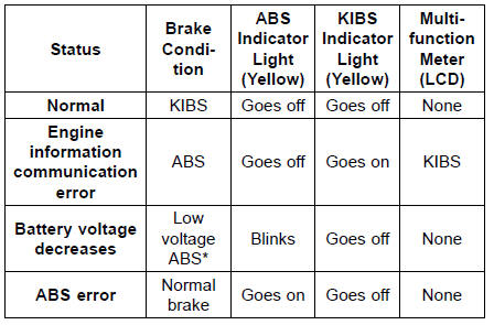
*: The mode of “Low voltage ABS” controls ABS while reducing the load to the battery.
NOTE
When the ABS indicator light is blinking, the ABS has been in the low voltage mode (insufficient battery voltage).
When it is in the low voltage mode, the KIBS system does not function, but the ABS functions. To recover the KIBS system, charge the battery. (see Refreshing Charge in the Electrical System chapter).
 Inquiries to Rider
 KIBS Hydraulic Unit Removal
Spark Plugs
The standard spark plug is shown in
the table. The spark plugs should be
replaced in accordance with the Periodic
Maintenance Chart.
Spark plug removal should be done
only by a competent mechanic following
the instructions in the Service Manual.
Spark Plug
A. Plug Gap ...
Chain Slack Adjustment
Remove the cotter pin, and loosen
the axle nut.
Loosen the left and right chain adjuster
locknuts.
A. Axle Nut
B. Cotter Pin
C. Adjuster
D. Locknut
If the chain is too loose, turn out the
left and right chain adjusters evenly.
If the chain is too tight, turn in the left
...
Crankshaft Removal
Split the crankcase (see Crankcase Splitting).
Remove:
Connecting Rod Big End Nuts [A]
Connecting Rod Big End Caps [B]
NOTE
Mark and record the locations of the connecting rods
and their big end caps so that they can be reassembled
in their original positions.
Remove the crank ...