
NOTICE
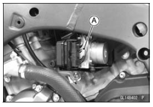
The KIBS hydraulic unit [A] has been adjusted and set with precision at the factory. Therefore, it should be handled carefully, never struck sharply, as with a hammer, or allowed to fall on a hard surface.
Be careful not to get water or mud on the KIBS hydraulic unit.
Drain the brake fluid through the bleed valve by pumping the brake lever and pedal.
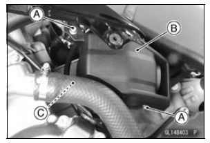
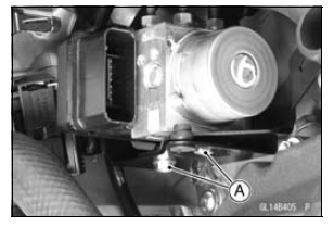
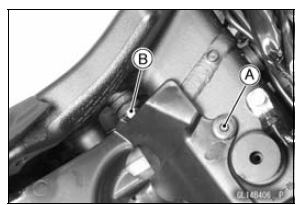
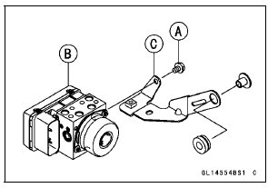
Clear the projection [C] from the bracket.
NOTICE
Clean all fittings on the KIBS hydraulic unit and the rear master cylinder because dirt around the banjo bolts could contaminate the brake fluid in the line during removal/installation.
Spread over a shop towel around the KIBS hydraulic unit before removing the brake line so that brake fluid does not leak on the parts.
NOTICE
Brake fluid quickly ruins painted plastic surfaces; any spilled fluid should be completely washed away immediately.
NOTE
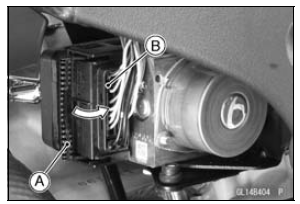
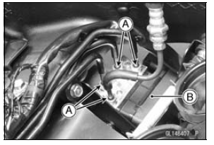
Remove the brake hoses and pipes according to each assembly of the exploded view.
NOTICE
The KIBS hydraulic unit has been adjusted and set with precision at the factory. Do not try to disassemble and repair the KIBS hydraulic unit.
 ABS and KIBS Indicator Lights (LED) Inspection
 KIBS Hydraulic Unit Installation
Periodic Maintenance Chart
The scheduled maintenance must be done in accordance with this chart to keep
the motorcycle in
good running condition. The initial maintenance is vitally important and must
not be neglected.
Periodic Inspection
#: Service more frequently when operating in severe conditions; dusty, ...
Loading and accessories information
WARNINGIncorrect loading, improper installation
or use of accessories,
or modification of your motorcyclemay
result in an unsafe riding
condition. Before you ride the
motorcycle, make sure it is not
overloaded and that you have
followed these instructions.
With the ...
Break-in
The first 1 600 km (1 000 mi) that the motorcycle is ridden is designated
as the
break-in period. If the motorcycle is not used carefully during this period, you
may
very well end up with a ÔÇťbroken downÔÇŁ instead of a ÔÇťbroken inÔÇŁ motorcycle after
a
few thousand kilometers.
The fol ...