
A clogged air cleaner restricts the engineŌĆÖs air intake, increasing fuel consumption, reducing engine power, and causing spark plug fouling.
This motorcycleŌĆÖs air cleaner element consists of a wet paper filter, which cannot be cleaned.
The air cleaner element must be replaced in accordance with the Periodic Maintenance Chart. In dusty, rainy, or muddy conditions, the air cleaner element should be serviced more frequently than the recommended interval.
NOTICE
Use only the recommended air cleaner element (Kawasaki part number 11013-0041). Using the other air cleaner elements will wear the engine prematurely or lower the engine performance.
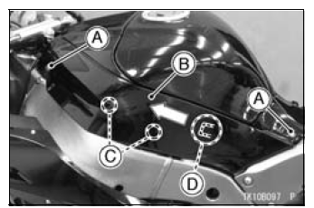
A. Bolts
B. Fuel Tank Side Cover
C. Projections
D. Tab
NOTE
On the left fuel tank side cover, pulling out it without disconnecting the connectors from the relay box.
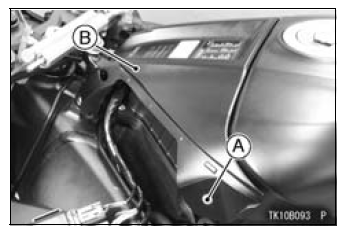
A. Bolts
B. Fuel Tank Front Cover
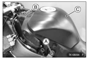
A. Bolts
B. Connector
C. Fuel Tank
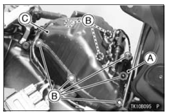
A. Connector Brackets
B. Screws
C. Air Cleaner Housing Cover
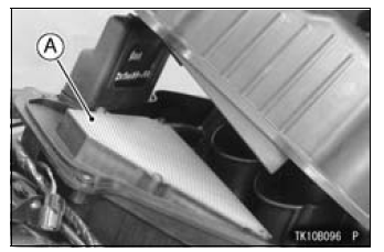
A. Air Cleaner Element
WARNING
|
NOTICE
If dirt gets through into the engine, excessive engine wear and possibly engine damage will occur.
Oil Draining
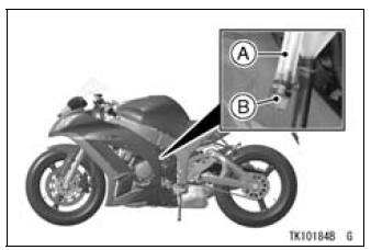
A. Transparent Hose
B. Plug
| WARNING Oil on tires will make them slippery and can cause an accident and injury. Be sure to install the plug in the drain hose after draining. |
 Exhaust Device
 Throttle Control System
Headlight Bulb Replacement
Turn the cover [A] counterclockwise, and remove it.
Disconnect the headlight connector [A].
Open the clamp [B], and remove the bulb.
NOTICE
When handling the quartz-halogen bulb, never
touch the glass portion with bare hands. Always
use a clean cloth. Oil contamination from hand ...
Coolant Deterioration Inspection
Remove the right lower fairing (see Lower Fairing Removal
in the Frame chapter).
Visually inspect the coolant in the reserve tank [A].
If whitish cotton-like wafts are observed, aluminum parts
in the cooling system are corroded. If the coolant is
brown, iron or steel parts are rusting. I ...
Fuel Tank Cleaning
WARNINGGasoline and low flash-point solvents can
be
flammable and/or explosive and cause severe
burns. Clean the tank in a well-ventilated area, and
take care that there are no sparks or flame anywhere
near the working area. Do not use gasoline
or low flash-point solvents t ...