
In accordance with the Periodic Maintenance Chart, it is very important to check the tightness of the bolts and nuts listed here. Also, check to see that each cotter pin is in place and in good condition. Please ask your authorized Kawasaki dealer for torque values.
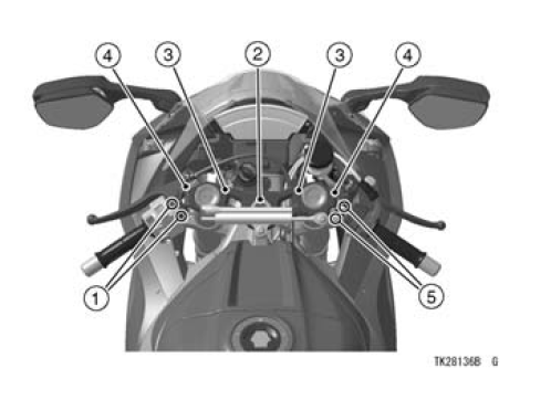
1. Clutch Lever Holder Bolts
2. Steering Stem Head Nut
3. Handlebar Clamp Bolts
4. Front Fork Clamp Bolts
5. Brake Lever Mounting Bolts
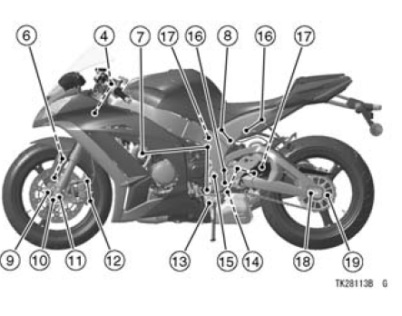
6. Front Fender Mounting Bolts
7. Engine Mounting Bolts and Nuts
8. Rear Frame Mounting Bolts
9. Brake Disc Mounting Bolts
10. Front Axle Clamp Bolts
11. Front Axle Nut
12. Caliper Mounting Bolts
13. Side Stand Bolt
14. Suspension Likage Tie-Rod Nuts
15. Swingarm Pivot Shaft Nut
16. Footpeg Mounting Bolts
17. Rear Shock Absorber Mounting Bolts
18. Rear Axle Nut
19. Rear Sprocket Nuts
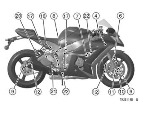
20. Silencer Mounting Bolt
21. Brake Pedal Bolt
22. Exhaust Pipe Mounting Bolt and Nuts
 Leather, Vinyl, and Rubber
 Storage
Exhaust Pipe Removal
Remove:
Radiator (see Radiator and Radiator Fan Removal in the
Cooling System chapter)
Exhaust Pipe Clamp Bolt [A] (Loosen)
Remove the exhaust pipe holder nuts [A], and pull out the
exhaust pipe [B] forward from the premuffler chamber.
...
Stick Coil Removal
Remove the air cleaner housing (see Air Cleaner Housing
Removal in the Fuel System (DFI) chapter).
Disconnect the stick coil connectors [A].
Pull out the stick coils [B] upward.
First, turn the stick coil by 90 degrees, and then pull it out
by twisting the coil head to the left and righ ...
Radiator Cap Inspection
Remove:
Radiator Cap (see Coolant Change in the Periodic Maintenance
chapter)
Check the condition of the bottom [A] and top [B] valve
seals and valve spring [C].
If any one of them shows visible damage, replace the cap
with a new one.
Install the cap [A] on a cooling system pr ...