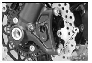

For the front caliper, be sure to install the collars [A].
Replace the washers on each side of hose fitting with new ones.

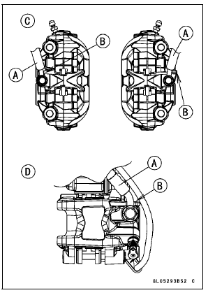
Touch the brake hoses [A] to the stopper [B] of the caliper.
Front Calipers [C] Rear Caliper [D]

| WARNING After servicing, it takes several applications of the brake lever or pedal before the brake pads contact the disc, which could result in increased stopping distance and cause an accident resulting in injury or death. Do not attempt to ride the motorcycle until a firm brake lever or pedal is obtained by pumping the lever or pedal until the pads are against the disc. |
Front Caliper Disassembly
Front Caliper Assembly
Rear Caliper Disassembly
Refer to the Caliper Rubber Parts Replacement in the Periodic Maintenance chapter.
Rear Caliper Assembly
Refer to the Caliper Rubber Parts Replacement in the Periodic Maintenance chapter.
 Rear Caliper Removal
 Caliper Fluid Seal Damage
Related Parts Locations
KIBS Control
1. ABS performance equivalent to the current model (enhanced braking
stability)
By monitoring front caliper hydraulic pressure, KIBS regulates pressure
increases reducing the tendency
of the rear to lift. Before the ABS system fully reacts, KIBS system prevents
the pressure ...
Oil Pump Removal
Remove:
Coolant (Drain, see Coolant Change in the Periodic
Maintenance chapter)
Engine Oil (Drain, see Engine Oil Change in the Periodic
Maintenance chapter)
Sidestand Switch Lead Connector [A] (Disconnect)
Bolt [B] and Water Pipe [C]
Water Pump Cover Bolts [D]
Water Pump Cover [E ...
Spark Plug Replacement
Remove the stick coils (see Stick Coil Removal in the
Electrical System chapter).
Remove the spark plugs using the 16 mm (0.63 in.) plug
wrench [A] vertically.
Replace the spark plug with new ones.
Standard Spark Plug
Type: NGK CR9EIA-9
Insert the spark plug vertically into the sp ...