
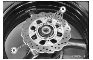
 Brake Disc
 Brake Disc Installation
CAN Communication (Transmission)/CAN Bus OFF Monitor Inspection (Service Code
b 57) CAN Communication (Reception) Monitor Inspection (Service Code b 58)
Remove:
Seat (see Seat Removal in the Frame chapter)
Immobilizer (Equipped Models)/Kawasaki Diagnostic
System Connector Cap [A]
Measure the CAN communication line resistance.
Immobilizer (Equipped Models)/Kawasaki Diagnostic
System Connector [A]
GY/BL Terminal [B]
LB Ter ...
Rear Wheel Removal
Raise the rear wheel off the ground with the stand [A].
Remove:
Cotter Pin [A]
Rear Axle Nut [B]
Washer [C]
Rear Axle [D] (from Right Side)
Remove the rear wheel rotation sensor from the caliper
bracket (see Rear Wheel Rotation Sensor Removal in the
Brakes chapter).
...
Oil Seal, Grease Seal
Do not remove pressed oil or grease seals unless removal
is necessary. Replace with new ones whenever removed.
Press new oil seals with manufacture and size marks facing
out. Make sure the seal is aligned properly when installing.
Apply specified grease to the lip of seal before installing ...