
The first 1 600 km (1 000 mi) that the motorcycle is ridden is designated as the break-in period. If the motorcycle is not used carefully during this period, you may very well end up with a “broken down” instead of a “broken in” motorcycle after a few thousand kilometers.
The following rules should be observed during the break-in period.
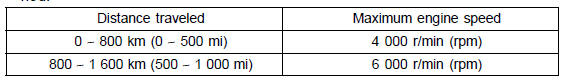
NOTE
When operating on public roadways, keep maximum speed under traffic low limits.
| WARNING New tires are slippery and may cause loss of control and injury. A break-in period of 160 km (100 miles) is necessary to establish normal tire traction. During break-in, avoid sudden and maximum braking and acceleration, and hard cornering. |
In addition to the above, at 1 000 km (600 mi) it is extremely important that the owner has the initial maintenance service performed by a competent mechanic following the procedures in the Service Manual.
 Front Footpeg Position
External Shift Mechanism Installation
Install the gear positioning lever [A] as shown in the figure.
Install:
Spring [B]
Washer [C]
Tighten:
Torque - Gear Positioning Lever Bolt [D]: 12 N·m (1.2 kgf·m,
106 in·lb)
Assemble:
Ratchet [A]
Pawls [B]
Pins [C]
Springs [D]
Install the shift ratchet ...
Throttle Body Assy Assembly
Before assembling, blow away dirt or dust from the throttle
body and delivery pipe assy by applying compressed air.
Replace the O-rings [A] of the joint pipe [B] with new ones.
Apply engine oil to the new O-rings, and insert it to the
delivery pipes [C].
Insert the joint pipe so th ...
Pressure Testing
Remove:
Upper Fairing Assembly (see Upper Fairing Assembly
Removal in the Frame chapter)
Radiator Cap [A]
Remove the radiator cap in two steps. First turn the cap
counterclockwise to the first stop. Then push and turn it
further in the same direction and remove the cap.
Install the ...
