
Special Tool - Hand Tester: 57001-1394
Charging Voltage 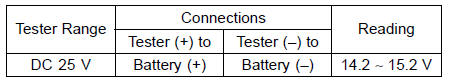
If the charging voltage is kept between the values given in the table, the charging system is considered to be working normally.
If the charging voltage is much higher than the values specified in the table, the regulator/rectifier is defective or the regulator/rectifier leads are loose or open.
If the charging voltage does not rise as the engine speed increases, then the regulator/rectifier is defective or the alternator output is insufficient for the loads. Check the alternator and regulator/rectifier to determine which part is defective.
 Alternator Rotor Installation
 Alternator Inspection
Clutch Installation
Apply engine oil to the needle bearing [A] and the sleeve
[B].
Install:
Needle Bearing
Sleeve
Install the clutch housing [A].
Fit the holes [B] and projections [C].
Engage the clutch housing gear and the crankshaft primary
gear.
Install the spacer [A] and the clutch ...
Crankshaft Sensor Removal
Remove:
Fuel Tank (see Fuel Tank Removal in the Fuel System
(DFI) chapter)
Crankshaft Sensor Lead Connector [A]
Remove:
Right Lower Fairing (see Lower Fairing Removal in the
Frame chapter)
Bolts [A]
Crankshaft Sensor Cover [B] and Gasket
Oil Pressure Switch Terminal [C]
...
Front Wheel Rotation Sensor Signal (Service Code 27)
Front Wheel Rotation Sensor Signal Inspection
The front wheel rotation sensor sends the signal to the
ECU through the KIBS hydraulic unit (KIBS equipped
models). For other than KIBS equipped models, the
signal is sent directly to the ECU.
The ECU uses the wheel rotation sensor signal for KTRC
...