
There are three types of alternator failures: short, open (wire burned out), or loss in rotor magnetism. A short or open in one of the coil wires will result in either a low output, or no output at all. A loss in rotor magnetism, which may be caused by dropping or hitting the alternator, by leaving it near an electromagnetic field, or just by aging, will result in low output.
Turn the ignition switch to OFF.
Remove the left upper inner fairing (see Upper Inner Fairing Removal in the Frame chapter).
Disconnect the alternator lead connector [A].
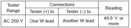
Connect the hand tester as shown in the table 1.
Special Tool - Hand Tester: 57001-1394
Start the engine.
Run it at the rpm given in the table 1.
Note the voltage readings (total 3 measurements).
Table 1 Alternator Output Voltage at 4 000 r/min (rpm)
If the output voltage shows the value in the table, the alternator operates properly. The regulator/rectifier is damaged.
If the output voltage shows a much lower reading than that given in the table, stop the engine and inspect the stator coil resistance.
Stop the engine.
Connect the hand tester as shown in the table 2.
Special Tool - Hand Tester: 57001-1394
Table 2 Stator Coil Resistance at 20°C (68°F)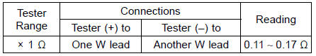
If there is more resistance than shown in the table, or no hand tester reading (infinity) for any two leads, the stator has an open lead and must be replaced. Much less than this resistance means the stator is shorted, and must be replaced.
Any hand tester reading less than infinity (∞) indicates a short, necessitating stator replacement.
If the stator coil has normal resistance, but the voltage check showed the alternator to be defective; then the rotor magnets have probably weakened, and the rotor must be replaced.
 Charging Voltage Inspection
 Regulator/Rectifier Inspection
Fuel Level Warning Indicator Light
: The fuel level warning
indicators
are activated when approximately 3.8 L
(1.0 US gal) of fuel remains as follows:
For models without KIBS:
A. Fuel Level Warning Indicator Light
B. “FUEL” Indication
The fuel level warning indicator light
( ) goes
on and “FUEL” blinks in the
...
Separator Operation Test
WARNINGGasoline is extremely flammable and can be
explosive
under certain conditions. Turn the ignition
switch OFF. Do not smoke. Make sure the area is
well-ventilated and free from any source of flame
or sparks; this includes any appliance with a pilot
light.
...
Exhaust Butterfly Valve Cable Removal
Remove the fuel tank (see Fuel Tank Removal in the Fuel
System (DFI) chapter).
Open the clamp [A] and free the cables.
Slide the dust covers [B].
Loosen the locknuts [A], and turn the adjusters [B] to give
the cable plenty of play.
Remove the clamp [A].
Remove the up ...