
The compression damping force adjuster and the rebound damping force adjuster are located on top of each front fork leg.
NOTICE
Do not force to turn the rebound and compression damping force adjuster from the fully seated position, or the adjusting mechanism may be damaged.
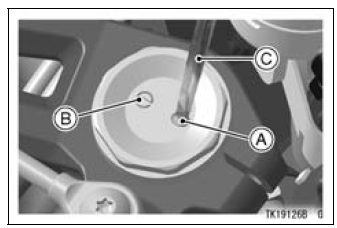
A. Compression Damping Force Adjuster (COM)
B. Rebound Damping Force Adjuster (TEN)
C. Screwdriver
Compression Damping Force Setting and Rebound Damping Force Setting
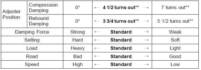
*: This position is the fully seated position (turned fully clockwise).
**: Out from the fully seated position (turned fully clockwise). This adjustment range may not exactly match the number shown in the table due to small tolerance of production.
The standard front fork setting positions are as follows:
Standard Setting Position (Front Fork)
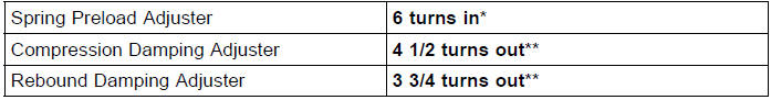
*: In from the fully seated position (turned fully counterclockwise) **: Out from the fully seated position (turned fully clockwise)
 Spring Preload Adjustment
 Rear Shock Absorber
Exploded View
14. Thermostat
15. Frame No. JKAZXT00JJA003074
or JKAZXCJ1
BA003074
G: Apply grease.
HG: Apply high-temperature grease.
L: Apply a non-permanent locking agent.
R: Replacement Parts
S: Follow the specified tightening sequence.
W: Apply water.
1. US, CA and CAL Models
2. Fra ...
Cooling System Flushing
Over a period of time, the cooling system accumulates
rust, scale, and lime in the water jacket and radiator. When
this accumulation is suspected or observed, flush the cooling
system. If this accumulation is not removed, it will clog
up the water passage and considerable reduce the efficiency
...
Rear Fender Front Removal
Remove:
Flap and Rear Fender Rear (see Flap and Rear Fender
Rear Removal)
Fuel Tank (see Fuel Tank Removal in the Fuel System
(DFI) chapter)
Battery (see Battery Removal in the Electrical System
chapter)
Exhaust Butterfly Valve Actuator (see Exhaust Butterfly
Valve Actuator Remova ...