
Note:
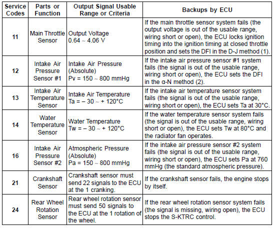
(1): D-J Method: When the engine load is light like at idling or low speed, the ECU determines the injection quantity by calculating from the throttle vacuum (vacuum sensor output voltage) and engine speed (crankshaft sensor output voltage). This method is called D-J method.
(2): α-N Method: As the engine speed increases, and the engine load turns middle to heavy, the ECU determines the injection quantity by calculating from the throttle opening (throttle sensor output voltage) and the engine speed. This method is called α-N method.
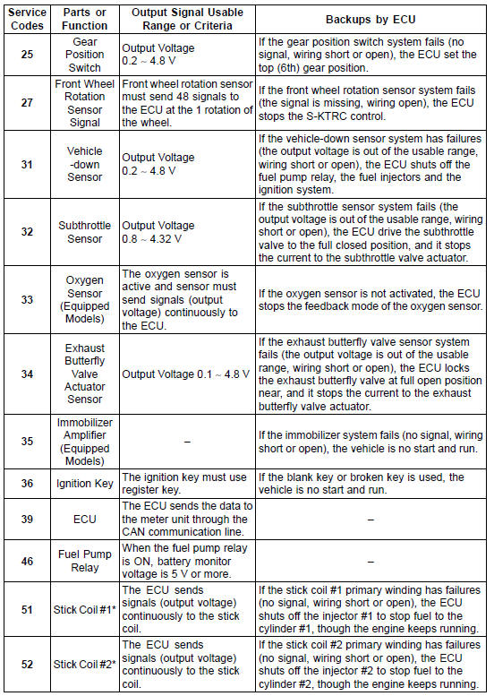
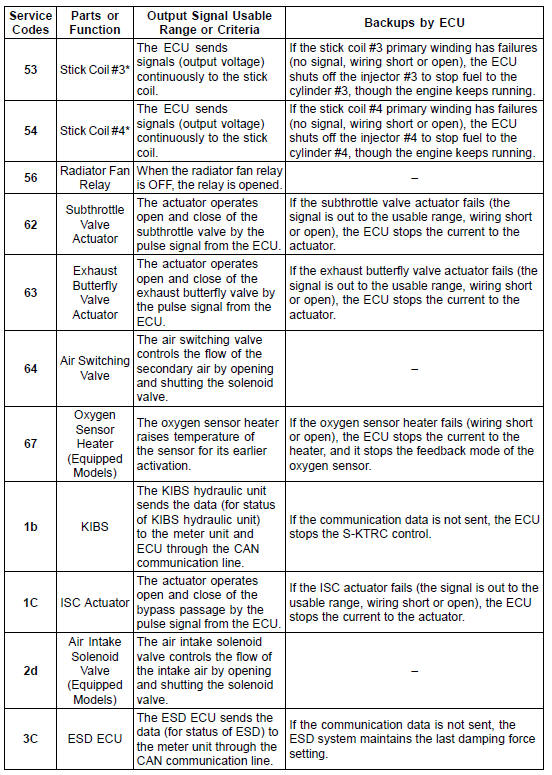
*: This depends on the number of stopped cylinders.
The main throttle sensor is a rotating variable resistor that change output voltage according to throttle operating. The ECU senses this voltage change and determines fuel injection quantity, and ignition timing according to engine rpm, and throttle opening.
Input Terminal [A]: BL Output Terminal [B]: V/W Ground Terminal [C]: BR/BK
 Service Code Erasing
Brake Light Switch Operation Inspection
Turn the ignition switch to ON.
The brake light (LED) [A] should go on when the brake
lever is applied or after the brake pedal is depressed
about 10 mm (0.39 in.).
If it does not, adjust the brake light switch.
Remove the front footpeg bracket (see Brake Pedal Removal
in the B ...
Fuel Pressure Inspection
NOTE
Be sure the battery is fully charged.
Remove:
Fuel Tank Covers (see Fuel Tank Removal)
Fuel Tank Bolts (see Fuel Tank Removal)
Primary Fuel Hose (see Fuel Hose Replacement in the
Periodic Maintenance chapter)
Be sure to place a piece of cloth around the fuel outlet
pipe of the ...
Stick Coil Installation
Apply a thin coat of grease [A] to the stick coils for easy
installation.
Insert the stick coils so that the coil heads align with the
lines [B] on the cylinder head cover.
NOTICE
Do not tap the coil head while installing the coil.
After installation, be sure the stick coils are ...
