
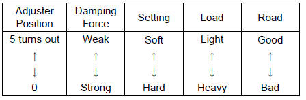
There are two adjustments you can make to the compression damping force.
High Speed Compression Damping Adjuster [A] Low Speed Compression Damping Adjuster [B]

The standard adjuster setting is the 1 3/4 turns out from the fully clockwise position.
High Speed Compression Damping Force Adjustment
NOTE
When turning the high speed compression damping force adjuster (outside), turn the low speed compression damping force adjuster (inside) too. But, the low speed compression damping force (setting position) dose not change.
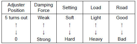
The standard adjuster setting is the 1 3/4 turns out from the fully clockwise position.
Low Speed Compression Damping Force Adjustment
 Rebound Damping Force Adjustment
 Spring Preload Adjustment
For Secondary Fuel Injectors
Remove the fuel tank (see Fuel Tank Removal).
Disconnect the secondary fuel injector connector [A].
Connect a digitalmeter to the terminals in each secondary
fuel injector [A].
Measure the secondary fuel injector resistance.
Secondary Fuel Injector Resistance
Standard: Abo ...
What Am I Responsible For?
You are responsible for maintaining your vehicle according to the maintenance
schedule shown in this owner’s manual.
You are responsible for notifying your dealer immediately if there is a problem,
and you, as the owner, will need to authorize the dealer to inspect the unit.
You will be re ...
Check 3-5: Warning Indicator Light (Red LED) (Oil Pressure Warning)
Inspection
Connect the leads in the same circuit as Check 3-2.
Connect the terminal [10] to the battery (–) terminal.
Check that the oil pressure warning symbol [A] and the
warning indicator light (Red LED) [B] go on.
If the indicator light does not go on, replace the meter unit.
...