
If the chain is too loose, turn out the left and right chain adjusters [D] evenly.
If the chain is too tight, turn in the left and right chain adjusters evenly, and kick the wheel forward.
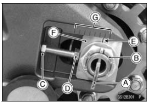
| WARNING Misalignment of the wheel will result in abnormal wear and may result in an unsafe riding condition. Be sure the wheel is properly aligned. |
Torque - Rear Axle Nut: 127 N·m (13.0 kgf·m, 94 ft·lb)
NOTE
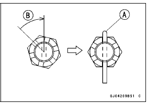
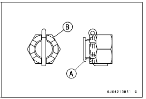
| WARNING A loose axle nut can lead to an accident resulting in serious injury or death. Tighten the axle nut to the proper torque and install a new cotter pin. |
 Drive Chain Slack Inspection
 Wheel Alignment Inspection
Premuffler Chamber Removal
Remove:
Muffler Body (see Muffler Body Removal)
Right Lower Fairing (see Lower Fairing Removal in the
Frame chapter)
Front Seat (see Front Seat Removal in the Frame chapter)
Oxygen Sensor (Equipped Models) (see Oxygen Sensor
Removal (Equipped Models) in the Electrical System
chapter ...
Air Cleaner Housing Removal
Remove the fuel tank (see Fuel Tank Removal).
Disconnect the secondary fuel hose [A] from the delivery
pipe of the nozzle assy [B] (see Fuel Hose Replacement
in the Periodic Maintenance chapter).
Disconnect the secondary fuel injector connectors [C].
Free the lead from the grooves [D].
...
Blank Key Detection (Service Code 36, Equipped Models)
Ignition Key Inspection
Register the ignition key correctly (see Key Registration
in the Electrical System chapter).
If the service code 36 appears again, the transponder in
the key is malfunction, replace it.
Immobilizer System Circuit
1. ECU
2. Ignition Switch
3. Immobilizer Ampl ...