

Disconnect the intake air pressure sensor #1 connector and connect the measuring adapter [A] between these connectors.
[B] Main Harness
[C] Intake Air Pressure Sensor #1
[D] Digital Meter
Special Tool - Measuring Adapter: 57001-1700
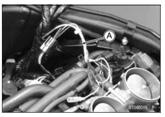
Intake Air Pressure Sensor #1 Output Voltage Connections to Adapter: Digital Meter (+) → Y (sensor Y/BL) lead Digital Meter (–) → BK (sensor BR/BK) lead
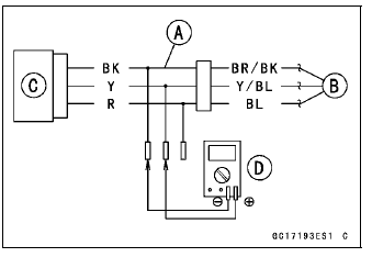
Output Voltage
Usable Range: DC 3.80  4.20 V at
standard
atmospheric pressure (101.32 kPa,
76 cmHg)
NOTE
The output voltage changes according to local atmospheric pressure.
If the reading is out of the usable range, replace the sensor.
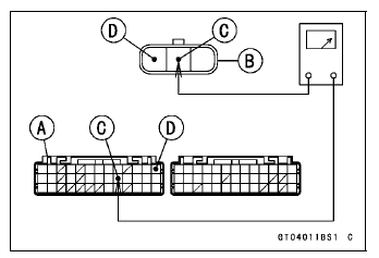
If the reading is within the usable range, remove the ECU and check the wiring for continuity between main harness connector.
Special Tool - Hand Tester: 57001-1394
Disconnect the ECU and sensor connectors.
Wiring Continuity Inspection
ECU Connector [A] ←→ Intake Air Pressure Sensor #1 Connector [B] Y/BL lead (ECU terminal 22) [C] BR/BK lead (ECU terminal 13) [D]
Turn the ignition switch to ON.
Measure the intake air pressure sensor #1 output voltage from various vacuum readings, while pulling the handle of the fork oil level gauge.
Check the intake air pressure sensor #1 output voltage, using the following formula and chart.
Suppose: Pg: Vacuum Pressure (Gauge) of Throttle Body Pl: Local Atmospheric Pressure (Absolute) measured by a barometer Pv: Vacuum Pressure (Absolute) of Throttle Body Vv: Sensor Output Voltage (V)
then Pv = Pl – Pg
For example, suppose the following data is obtained: Pg = 8 cmHg (Vacuum Gauge Reading) Pl = 70 cmHg (Barometer Reading) Vv = 3.2 V (Digital Meter Reading)
then Pv = 70 – 8 = 62 cmHg (Absolute)
Plot this Pv (62 cmHg) at a point [1] on the chart and draw a vertical line through the point. Then, you can get the usable range [2] of the sensor output voltage.
Usable range = 3.08  3.48 V
Plot Vv (3.2 V) on the vertical line. → Point [3]
Results: In the chart, Vv is within the usable range and the sensor is normal.
If the reading is out of the usable range, replace the sensor.
If the reading is within the usable range, check the ECU for its ground and power supply (see ECU Power Supply Inspection in the Fuel System (DFI) chapter).
If the ground and power supply are good, replace the ECU (see ECU Removal/Installation in the Fuel System (DFI) chapter).
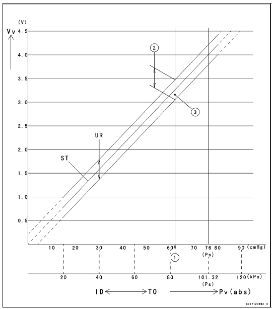
ID: Idling Ps: Standard Atmospheric Pressure (Absolute) Pv: Throttle Vacuum Pressure (Absolute) ST: Standard of Sensor Output Voltage (V) TO: Throttle Full Open UR: Usable Range of Sensor Output Voltage (V) Vv: Intake Air Pressure Sensor #1 Output Voltage (V) (Digital Meter Reading)
Intake Air Pressure Sensor #1 Circuit
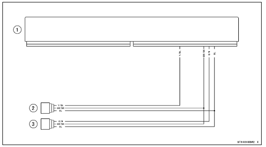
1. ECU
2. Intake Air Pressure Sensor #1
3. Intake Air Pressure Sensor #2
 Intake Air Pressure Sensor #1 Input Voltage Inspection
Electrical Wiring
Wiring Inspection
Visually inspect the wiring for signs of burning, fraying,
etc.
If any wiring is poor, replace the damaged wiring.
Pull each connector [A] apart and inspect it for corrosion,
dirt, and damage.
If the connector is corroded or dirty, clean it carefully. If it
is da ...
Amplifier Input Voltage Inspection
NOTE
Be sure the battery is fully charged.
Turn the ignition switch to OFF.
Remove the upper fairing (see Upper Fairing Removal in
the Frame chapter).
Do not disconnect the connectors.
Connect a digital meter to the amplifier connector [A] with
needle adapter set.
Special To ...
Spring Plate Free Play Adjustment
NOTE
The free play adjustment is performed by replacing the
steel plate(s).
Measure the clutch spring plate free play (see Clutch
Spring Plate Free Play Measurement), and then replace
the steel plate(s) which brings the free play within the
usable range.
Spring Plate Free Play
Usable ...