
NOTE
These procedures are explained on the assumption that the intake and exhaust systems of the engine are in good condition.
NOTE
When the engine is running, the ECU detects the service code 16. But the engine synchronization can be inspected correctly.
Special Tool - Vacuum Gauge: 57001-1369
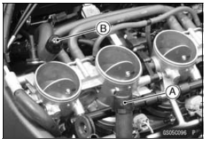
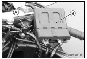
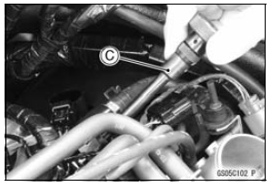
Fuel Pump Lead Connector [A] Extension Tube [B]
Special Tool - Extension Tube: 57001-1578
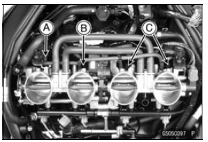
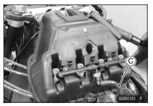
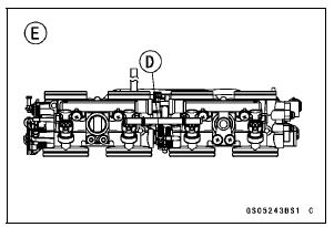
Intake Air Temperature Sensor [A] ECU [B] ESD ECU (ZX1000JD/KD) Secondary Fuel Hose [C] (see Fuel Hose Replacement)
NOTE
When the ignition switch is turned ON without the intake air temperature sensor, the ECU detects the service code 13. Then the ECU starts the fail-safe (see Self-diagnosis Outline in the Fuel System (DFI) chapter).
In this case, the engine vacuum synchronization can not be inspected correctly.
The engine vacuum synchronization is inspected with the air cleaner housing removed and the engine started.
The secondary fuel injectors are operating with following conditions.
1. The engine speed is more than 6 000 r/min (rpm).
2. The throttle opening is more than 12°.
| WARNING Gasoline is extremely flammable and can be explosive under certain conditions, especially when atomized by the fuel injector nozzle. To prevent a fire or explosion, be sure the secondary fuel injector connectors are disconnected before starting the engine so that fuel cannot be sprayed by the injectors. |
Idle Speed Standard: 1 100 ±50 r/min (rpm)
If the idle speed is out of the specified range, inspect the idle speed control valve (see Idle Speed Control Valve Inspection in the Self-Diagnosis System chapter).
NOTICE
Do not measure the idle speed by the meter unit.
Throttle Body Vacuum Standard: 30.7 ±1.33 kPa (230 ±10 mmHg) at idle speed
View from Front [B]
Special Tool - Pilot Screw Adjuster, D [C]: 57001-1588

NOTE
Therefore, the secondary fuel injectors do not operate while adjusting the engine vacuum synchronization. If raising the engine speed more than 6 000 r/min (rpm), the engine may not operate smoothly.
View from Rear [E]
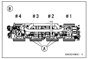
If all vacuums are within the specification range, finish the engine vacuum synchronization.
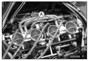
If any vacuum can not be adjusted within the specification, remove the bypass screws #1 ∼ #4 and replace them with new ones.
Bypass Screw
Spring [B]
Washer [C]
O-ring [D]
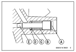
If any carbons accumulate, wipe the carbons off from the hole, using a cotton pad penetrated with a high flash-point solvent.
NOTICE
Do not over-tighten the bypass screw. The tapered portion [E] of the bypass screw could be damaged.
NOTE
A throttle body has different “turns out” of the bypass screw for each individual unit. On setting the bypass screw, use the “turns out” determined during disassembly.
If the vacuums are correct, check the output voltage of the main throttle sensor (see Main Throttle Sensor Output Voltage Inspection in the Self-Diagnosis System chapter).
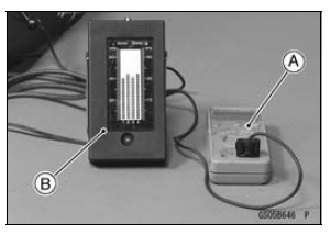
Special Tool - Throttle Sensor Setting Adapter: 57001 -1538
Main Throttle Sensor Output Voltage
Connections to Adapter: Degital Meter (+) → R (sensor L) lead
Degital Meter (‚Äì) → BK (sensor V/W) lead
Standard: DC 0.64 ∼ 0.68 V at idle throttle opening
If the output voltage is out of the standard, check the input voltage of themain throttle sensor (see Main Throttle Sensor Input Voltage Inspection in the Self-Diagnosis System chapter).
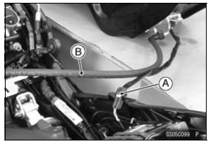
Run the vacuum hose according to Cable, Wire, and Hose Routing section in the Appendix chapter.
 Throttle Control System Inspection
 Idle Speed Inspection
Air Cleaner Housing Installation
For ZX1000JD/KD, be sure to install the pad [A].
Install the clamp bolt heads [A] inside as shown in the
figure.
Install the air cleaner housing on the throttle body assy.
Push in the ducts [B] touch the stoppers [C] of the throttle
body.
Be sure the hoses are routed correctly ...
Brake Light Switches
When either the front or rear brake is
applied, the brake light goes on. The
front brake light switch requires no adjustment,
but the rear brake light switch
should be adjusted in accordance with
the Periodic Maintenance Chart.
Inspection
Turn the ignition key to “ON”.
The brake ligh ...
Tie-Rod and Rocker Arm Bearing Removal
Remove:
Tie-Rod (see Tie-Rod Removal)
Rocker Arms (see Rocker Arm Removal)
Swingarm (see Swingarm Removal)
Sleeves [A]
Oil Seals [B]
Remove the needle bearings [C], using the bearing remover
head and bearing remover shaft.
Special Tools - Bearing Remover Head,
15 ×
17: ...