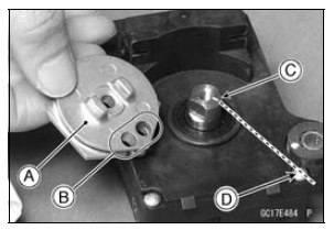

Make sure that the groove on the shaft is pointing toward the center of the screw [D].
If the shaft position is incorrect, refer to the following NOTE and procedures to electrically adjust the shaft position.

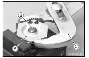
Torque - Exhaust Butterfly Valve Actuator Pulley Bolt: 4.9 N·m (0.50 kgf·m, 43 in·lb)

NOTICE
If the pulley bolt is tightened without holding, the actuator damage will occur.
41.7° ±7° [B]
This position is original position of the pulley.
NOTE
Correct the position electrically after confirming the use is discontinued and there is no damage when differing from the angle of shown in the figure.

NOTICE
Do not correct the pulley position with the tool, forcibly. The actuator damage will occur.
If the pulley angle is wrong, adjust the angle as follows.
Connect: 2 pins Connector 3 pins Connector
Turn the ignition switch to ON.
Confirm the pulley turns clockwise or counterclockwise then it stops at the original position.
If the pulley position has not been returned to the original position, electrically adjust the shaft position as follows.

Remove: 2 pins Connector 3 pins Connector
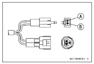
Turn the pulley to the original position by turning it clockwise or counterclockwise by connecting the battery to the 2 pin connector terminals. To turn the pulley gradually, intermittently connect the battery positive (+) terminal to the 2 pin connector terminal while connecting the battery negative (–) terminal to the connector.
Pink (–) lead terminal [A] Gray (+) lead terminal [B]
Clockwise: Pink (–) lead terminal to battery (–) terminal Gray (+) lead terminal to battery (+) terminal
Counterclockwise: Pink (–) lead terminal to battery (+) terminal Gray (+) lead terminal to battery (–) terminal
Reconnect the 2 pins connector and 3 pins connector, and turn the ignition switch ON.
Make sure that the pulley turns clockwise and then counterclockwise.
The pulley should returns to the original position.
Turn the ignition switch OFF.
If the pulley does not return to the original position, check the exhaust butterfly valve actuator resistance (see Exhaust Butterfly Valve Actuator Resistance Inspection).

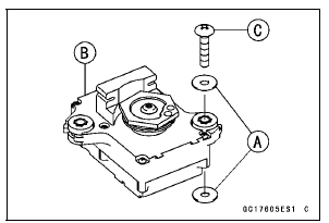
 Exhaust Butterfly Valve Actuator Removal
 Exhaust Butterfly Valve Actuator Inspection
Passenger’s Seat Removal
Remove the passenger’s seat by inserting
the ignition key into the seat
lock, and turning it clockwise.
A. Seat Lock
B. Ignition Key
C. Passenger’s seat
D. Pull up
NOTE
When removing the passenger’s
seat, pull it up while turning the key. ...
Piston Wear Inspection
Measure the outside diameter [A] of each piston 5 mm
(0.20 in.) [B] up from the bottom of the piston at a right
angle to the direction of the piston pin.
If the measurement is under service limit, replace the piston.
Piston Diameter
Standard: 75.959 75.974 mm
(2.9905 2.9911 in.)
...
Warning Indicator Light (LED)
Light (LED) Inspection
The warning indicator light (LED) [A] is used for the FI indicator,
immobilizer indicator (immobilizer equipped models),
water temperature warning indicator and oil pressure
warning indicator.
In this model, the warning indicator light (LED) (FI/immobilizer)
goes ...